Flowerpot batch soil covering device for potted plants

A batch and soil-covering technology, which is applied in the field of batch soil-covering device for flower pots for potted plants, can solve the problems of low work efficiency, lumpy soil, inconvenient planting, etc., and achieve the effect of improving work efficiency

Pending Publication Date: 2021-06-22
涂曦雯
View PDF14 Cites 5 Cited by
  • Summary
  • Abstract
  • Description
  • Claims
  • Application Information

AI Technical Summary

Problems solved by technology

[0006] In order to overcome the above-mentioned method, the working efficiency is low during operation, and the soil cannot be pulverized, which may easily cause some soil to be in the form of soil lumps, which is relatively inconvenient for planting. The technical problem to be solved by the present invention is Provides a potted flower pot batch soil covering device capable of covering multiple flower pots at one time, improving work efficiency, and crushing soil clods

Method used


Image

  • Flowerpot batch soil covering device for potted plants
  • Flowerpot batch soil covering device for potted plants
  • Flowerpot batch soil covering device for potted plants

Examples


Embodiment 1

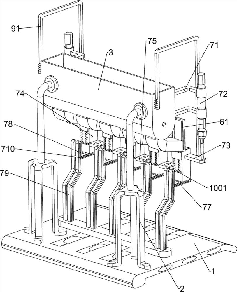
[0033] A kind of flower pot bulk covering device for potted plants, such as Figure 1-4 As shown, it includes a bottom frame 1, a first fixed frame 2, a material box 3 and a support frame 4. The left and right sides of the top of the bottom frame 1 are connected with the first fixed frame 2, and the two first fixed frames 2 are connected. There is a material box 3, and the bottom of the material box 3 is evenly spaced with a plurality of discharge ends. A pulverizing mechanism 5 and a blocking mechanism 6 are provided.

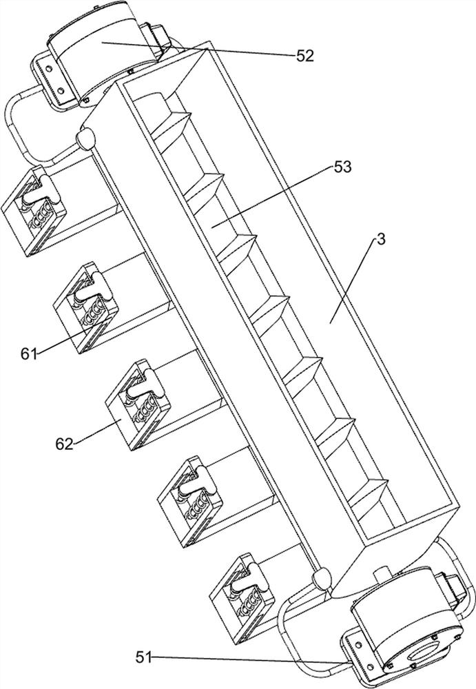
[0034] The crushing mechanism 5 includes a second fixed mount 51, a servo motor 52 and a stirring rod 53, and the left and right sides of the material box 3 are connected with a second fixed mount 51, and the second fixed mount 51 is equipped with a servo motor 52, which is a material box 3. A stirring rod 53 is rotatably connected to the top, and both sides of the stirring rod 53 are connected to the output shafts of two servo motors 52 respectively.

[003...

Embodiment 2

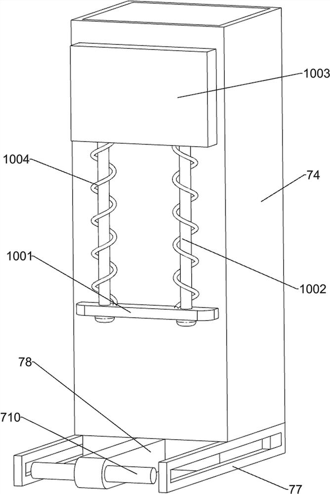
[0038] On the basis of Example 1, such as Figure 5-6Shown, also includes unloading mechanism 7, and unloading mechanism 7 includes the 3rd fixed frame 71, cylinder 72, first fixed plate 73, receiving rack 74, the second fixed plate 75, fixed rod 76, the second guide Sliding frame 77, the second material blocking plate 78, the 3rd guide carriage 79 and guide slide bar 710, are all connected with the 3rd fixed mount 71 on the left and right sides of material box 3, and cylinder 72 is installed on the 3rd fixed mount 71, The telescopic rods of the two cylinders 72 are connected with a first fixed plate 73, and a plurality of receiving racks 74 are evenly spaced between the two first fixed plates 73, and the receiving rack 74 cooperates with the first material blocking plate 62, The rear side of the material receiving frame 74 is provided with a material inlet, and the material inlets of a plurality of material receiving frames 74 are respectively aligned with a plurality of disc...

Embodiment 3

[0043] On the basis of Example 2, such as Figure 6 and Figure 8 As shown, it also includes a flip mechanism 9, and the flip mechanism 9 includes a third rack 91, a second support block 92, a second connecting shaft 93, a cover plate 94, a torsion spring 95 and a third spur gear 96, the first fixed The plate 73 is connected with a third rack 91, and is connected with two second support blocks 92 at the upper part of the rear side of the material box 3, and a second connecting shaft 93 is connected in rotation between the two second support blocks 92, and the second connection A cover plate 94 is connected to the shaft 93, a torsion spring 95 is connected between the cover plate 94 and the second support block 92, a third spur gear 96 is connected to both sides of the second connection shaft 93, and the two third spur gears 96 are respectively Engages with two third racks 91 .

[0044] The first fixed plate 73 can drive the third rack 91 to move up and down when moving up an...


PUM


Abstract

The invention relates to a soil covering device, in particular to a flowerpot batch soil covering device for potted plants. The technical problem to be solved by the invention is how to design the flowerpot batch soil covering device for potted plants, which can cover a plurality of flowerpots with soil at one time, improve the working efficiency and crush soil blocks. In order to solve the technical problem, the flowerpot batch soil covering device for potted plants comprises a bottom frame, wherein first fixing frames are connected to the two sides of the top of the bottom frame; a material containing box which is connected between the two first fixing frames; a supporting frame which is connected to one side of the top of the bottom frame; a crushing mechanism which is arranged on the material containing box; and a material blocking mechanism which is arranged on the material containing box. According to the flowerpot batch soil covering device for the potted plants, the crushing mechanism and the material blocking mechanism cooperate to carry out soil covering on the flowerpots, so that the effect of carrying out soil covering on the flowerpots is achieved.

Description

technical field [0001] The invention relates to a soil covering device, in particular to a batch soil covering device for flowerpots for potted plants. Background technique [0002] Flowerpot, a kind of container for planting flowers, is in the shape of a rounded platform or a chamfered platform with a large mouth and a small bottom end. The flowerpots for planting flowers are in various forms and sizes. Flower producers or flower growers can choose according to the characteristics of flowers and According to the needs and characteristics of flower pots, choose flower pots. According to different materials, they can be divided into many types. Some merchants will add soil to the flower pots when they sell flower pots. There is no need for buyers to add soil, which makes buyers more comfortable. convenient. [0003] At present, the way of covering the flower pots is usually to manually collect the soil, and then use a shovel to shovel the soil into the inside of the flower p...

Claims


Application Information

Patent Timeline
Patent Type & Authority Applications(China)
IPC IPC(8): A01G9/08B01F13/10
CPCA01G9/081B01F33/805B01F33/83B01F2101/04
Inventor 涂曦雯
Owner 涂曦雯
Why Eureka
Try Eureka