Low-tower small-granule making process and low-tower small-granule making system for fertilizer
A technology of fertilizer granules and small granules, applied in fertilizer mixtures, solid/semi-solid fertilizers, granulation in rotating discs/pots, etc., can solve the problems of impurity clogging, low cost, etc. The effect of solving impurity blockage
- Summary
- Abstract
- Description
- Claims
- Application Information
AI Technical Summary
Problems solved by technology
Method used
Image
Examples
Embodiment 1
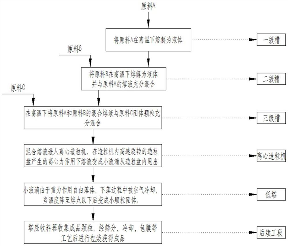
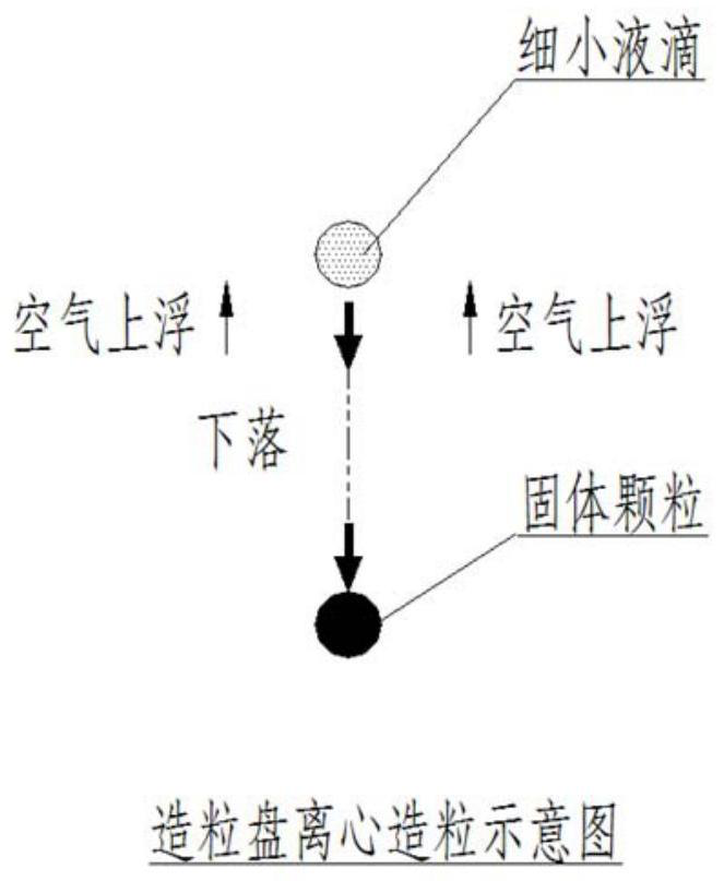
[0084] Such as Figure 1 to Figure 3 Shown, the low tower of a kind of fertilizer makes small granule technique, and this technique comprises the following steps:
[0085] S1: Add the solid particle mixture raw material A, raw material B and raw material C into the first-level tank 11, the second-level tank 12 and the third-level tank 13, and melt it into a slurry under the action of a high temperature of 120-170 ° C, and then step by step After dissolving and mixing, a mixed slurry of raw material A, raw material B and raw material C is formed in the tertiary tank 13; There is a steam heating device, and the steam heating device is equipped with a temperature sensor and a steam inlet regulating valve to control the amount of heating steam; when the temperature sensor detects that the temperature of the slurry is higher than the set temperature, the steam inlet regulating valve reduces the opening, reducing The amount of steam used for heating reduces the temperature; when th...
Embodiment 2
[0131] One of the embodiments of the present invention, such as Figure 15 As shown, the main technical solutions of this embodiment are the same as those of Embodiment 1, and the features not explained in this embodiment are explained in Embodiment 1, and will not be repeated here. The difference between this embodiment and Embodiment 1 is that: the inner lower end of the tower is provided with a cooling device, the cooling device is an air-cooled cooling device, the cooling device is an air-cooled cooling device 25b, and the air-cooled cooling device 25b Including an electric regulating valve 253b, an induced draft fan 252b and a heat exchange fin 24b; the electric regulating valve 253b and the induced draft fan are arranged outside the tower body and the electric regulating valve 253b is connected to the inlet of the induced draft fan 252b; multiple The heat exchange fins 24b are vertically arranged at the lower end of the tower body 2, and the two ends of each heat exchang...
Embodiment 3
[0133] One of the embodiments of the present invention, such as Figure 16 with Figure 17 As shown, the main technical solution of this embodiment is the same as that of Embodiment 1 or Embodiment 2, and the features not explained in this embodiment are explained in Embodiment 1 or Embodiment 2, and will not be repeated here. The difference between this embodiment and Embodiment 1 or Embodiment 2 is that it also includes a plurality of receiving hoppers 27 arranged at the bottom of the granulation tower, and a first belt conveyor 24 is correspondingly provided under each receiving hopper 27, A plurality of belt conveyors are arranged in parallel; a second belt conveyor 29 is arranged near the same end of each of the first belt conveyors 24; The first belt conveyor 24 is transported to the second belt conveyor 29, and the second belt conveyor 29 transports the fertilizer granules to the subsequent working section. A cooling fan 28 is provided above the receiving hopper 27 fo...
PUM
| Property | Measurement | Unit |
|---|---|---|
| Height | aaaaa | aaaaa |
| Diameter | aaaaa | aaaaa |
| Melting point | aaaaa | aaaaa |
Abstract
Description
Claims
Application Information
 - R&D
- Intellectual Property
- Life Sciences
- Materials
- Tech Scout
- Unparalleled Data Quality
- Higher Quality Content
- 60% Fewer Hallucinations
Browse by: Latest US Patents, China's latest patents, Technical Efficacy Thesaurus, Application Domain, Technology Topic, Popular Technical Reports.
© 2025 PatSnap. All rights reserved.Legal|Privacy policy|Modern Slavery Act Transparency Statement|Sitemap|About US| Contact US: help@patsnap.com


