Integrated structure of detector and integration method

An integrated method and detector technology, applied in the direction of semiconductor devices, electric solid devices, radiation control devices, etc., can solve the problems of inaccurate alignment, reduce the length of interconnection lines, reduce the size of the system, and improve the quantum effect Effect

Pending Publication Date: 2021-06-22
GUANGDONG GREATER BAY AREA INST OF INTEGRATED CIRCUIT & SYST
View PDF8 Cites 0 Cited by
  • Summary
  • Abstract
  • Description
  • Claims
  • Application Information

AI Technical Summary

Problems solved by technology

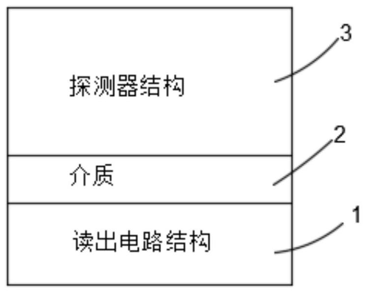
[0004] The main purpose of the present invention is to provide a detector integration method, the method is to bond the substrate without the detector structure in the electronic circuit

Method used


Image

  • Integrated structure of detector and integration method
  • Integrated structure of detector and integration method
  • Integrated structure of detector and integration method

Examples


Embodiment Construction

[0018] Hereinafter, embodiments of the present disclosure will be described with reference to the drawings. It should be understood, however, that these descriptions are exemplary only, and are not intended to limit the scope of the present disclosure. Also, in the following description, descriptions of well-known structures and techniques are omitted to avoid unnecessarily obscuring the concept of the present disclosure.

[0019] Various structural schematic diagrams according to embodiments of the present disclosure are shown in the accompanying drawings. The figures are not drawn to scale, with certain details exaggerated and possibly omitted for clarity of presentation. The shapes of the various regions and layers shown in the figure, as well as their relative sizes and positional relationships are only exemplary, and may deviate due to manufacturing tolerances or technical limitations in practice, and those skilled in the art will Regions / layers with different shapes, s...


PUM


Abstract

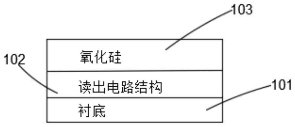
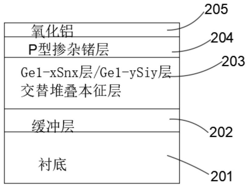
The invention relates to an integrated structure of a detector and a method thereof. The integration method of the detector comprises the following steps: manufacturing an electronic circuit structure on a first substrate, and then forming a first dielectric layer on the surface of the electronic circuit structure to obtain a substrate A; sequentially forming a germanium buffer layer, a stacking intrinsic layer, a P-type doped germanium layer and a second dielectric layer on the surface of a second substrate from bottom to top to obtain a substrate B, wherein the stacked intrinsic layer is formed by alternately and repeatedly stacking Ge<1-x>Snx layers and Ge<1-y>Siy layers for n times, x is greater than 0 and less than or equal to 0.3, y is greater than 0 and less than or equal to 0.3, and n is greater than or equal to 1; bonding the substrate A and the substrate B; removing the second substrate and the germanium buffer layer after bonding, forming an N-type doped germanium layer on the surface of the stacked intrinsic layer, and manufacturing a detector structure; and enabling the electronic circuit structure and the detector structure are interconnected. According to the invention, the substrate on which the detector is not manufactured is bonded in the electronic circuit structure substrate, so that the integration process is simplified, the integration level is improved, and the problem that accurate alignment cannot be realized is solved.

Description

technical field [0001] The invention relates to the field of semiconductor production technology, in particular to an integrated structure and integrated method of a detector. Background technique [0002] Photonics integration can combine the advantages of photons and electronic circuits at the same time, break the limitations of power consumption and information transmission in the traditional microelectronics field, and promote the development of the information industry. In the optoelectronic integration scheme, silicon-based monolithic optoelectronic integration (optoelectronic integrated chip) has the ability to realize most photonic devices (including lasers, photodiodes, detectors, etc.) and electronic devices (including amplifiers, signal conditioners, readers, etc.) Circuits, etc.) integration, compatibility with traditional microelectronics manufacturing processes, and the advantages of large-scale mass production have good research and application prospects. [...

Claims


Application Information

Patent Timeline
IPC IPC(8): H01L31/18H01L31/028H01L31/105H01L27/144
CPCH01L31/1804H01L31/1892H01L31/105H01L31/028H01L27/1443Y02P70/50
Inventor 亨利·H·阿达姆松王桂磊罗雪孔真真戚璇
Owner GUANGDONG GREATER BAY AREA INST OF INTEGRATED CIRCUIT & SYST
Why Eureka
Try Eureka