A high voltage pn bridge gate drive circuit

A gate drive circuit and drive circuit technology, applied in the direction of electrical components, output power conversion devices, etc., can solve the problems of complex structure of PN bridge drive circuit and impossibility to realize thin gate oxide device technology, so as to reduce the complexity of circuit structure, Effects of layout size reduction and static power reduction

Active Publication Date: 2022-06-28
国硅集成电路技术(无锡)有限公司
View PDF11 Cites 0 Cited by
  • Summary
  • Abstract
  • Description
  • Claims
  • Application Information

AI Technical Summary

Problems solved by technology

[0005] Aiming at the problem that the structure of the traditional PN bridge driving circuit is complex and cannot be realized in the thin gate oxide device process, the present invention proposes a new type of PN bridge driving circuit, which can not only reduce the number of LDOs, but also can be used in the small size thin gate oxide BCD process realized in

Method used


Image

  • A high voltage pn bridge gate drive circuit
  • A high voltage pn bridge gate drive circuit
  • A high voltage pn bridge gate drive circuit

Examples


Embodiment Construction

[0031] The preferred embodiments of the present invention will be described below with reference to the accompanying drawings. It should be understood that the preferred embodiments described herein are only used to illustrate and explain the present invention, but not to limit the present invention.

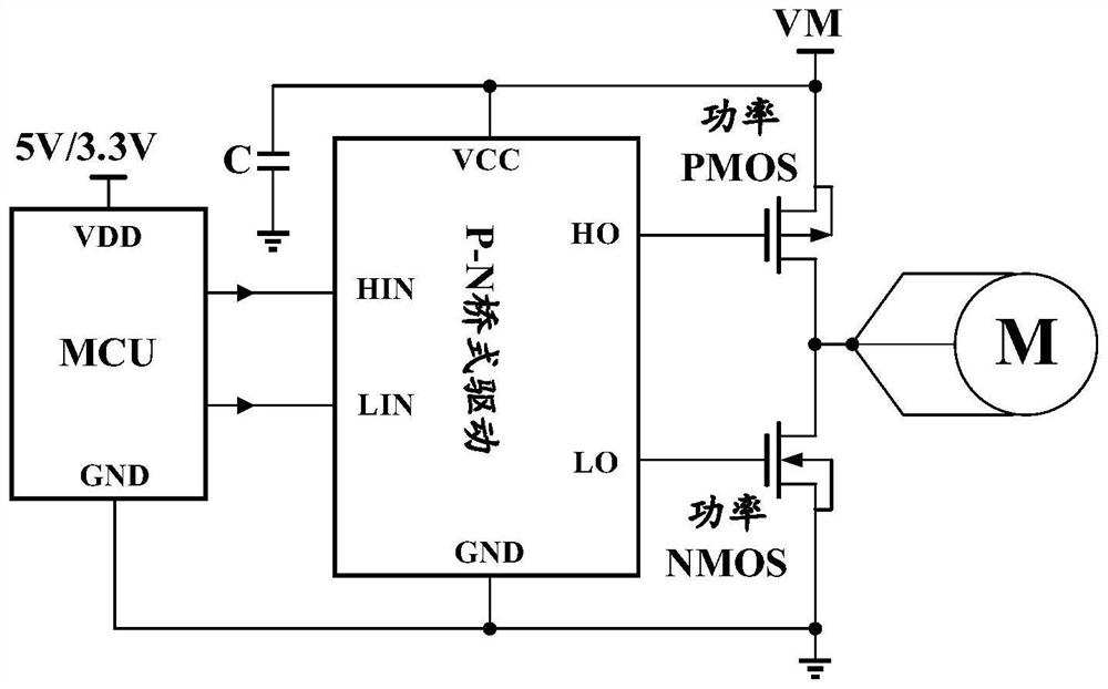
[0032] The invention provides a high-voltage PN bridge gate drive circuit for driving a PN bridge. The PN bridge includes a high-side load high-voltage PMOS transistor and a low-side load high-voltage NMOS transistor, and the drive circuit includes an input stage circuit, a voltage regulator circuit, and a level conversion circuit. , gate voltage control circuit, I-V conversion circuit, output voltage detection circuit, the first power device PMOS tube and the second power device NMOS tube, the voltage regulator circuit is connected between VCC and the input stage circuit to supply power for the input stage circuit, The input end of the input stage circuit is the input end of the...


PUM


Abstract

A high-voltage PN bridge gate drive circuit, using a voltage stabilizing circuit to reduce the power supply voltage to supply power to the input stage circuit, using a level conversion circuit to convert the signal of the input stage into a voltage that can drive a high-voltage thin gate oxide PMOS tube, and using a resistor to divide the voltage Judging the relationship between the output voltage and the set voltage, when used to drive the power PMOS tube, when the output voltage of the gate drive circuit of the PMOS tube is lower than the set value, the current capability of the drive tube NMOS tube is reduced or even turned off , so that the output voltage rises and dynamically stabilizes around the set value; similarly, when used to drive a power NMOS tube, the output voltage rises and dynamically stabilizes around the set value. The set value can be between GND and VCC Any value between, and determined by the resistance ratio and the threshold voltage of the MOS tube. The invention reduces the complexity of the circuit structure and reduces the power consumption, which is beneficial to improving the integration degree of the driving chip and reducing the cost.

Description

technical field [0001] The invention belongs to the technical field of medium and high voltage power integrated circuits, relates to a medium and high voltage motor drive control technology, and is a high voltage PN bridge gate drive circuit. Background technique [0002] Medium and high voltage motor drives are usually driven by a bridge structure formed by a combination of PMOS transistors and NMOS transistors. The bridge is called a PN bridge in academia and industry. In low-voltage applications, the inverter is the simplest PN bridge, and its driving method is also very simple. The PN bridge can be directly driven by the "0" and "1" level voltages of TTL logic. In order to prevent the shoot-through loss at the moment of switching the PN bridge switch, the PMOS transistor and the NMOS transistor in the PN bridge are usually driven separately, and the zero-voltage switching technology is used to reduce the loss of the system. A typical application circuit such as figure ...

Claims


Application Information

Patent Timeline
Patent Type & Authority Patents(China)
IPC IPC(8): H02M1/088H02M1/32
CPCH02M1/088H02M1/32
Inventor 张允武陆扬扬
Owner 国硅集成电路技术(无锡)有限公司
Why Eureka
Try Eureka