
A kind of automatic pipe chamfering machine

A fully automatic, chamfering machine technology, applied in the field of chamfering machines, can solve the problems of small scope of application and single function, and achieve the effect of preventing splashing, high degree of automation, and good work continuity

Active Publication Date: 2022-03-22
HANGZHOU PANASIA SANITARY WARE
View PDF8 Cites 0 Cited by
  • Summary
  • Abstract
  • Description
  • Claims
  • Application Information

AI Technical Summary

Problems solved by technology

[0004] At present, a single pipe fitting chamfering mechanism can only process one of the inner chamfering or outer chamfering of pipe fittings, which has a single function and a small scope of application.

Method used


Image

  • A kind of automatic pipe chamfering machine
  • A kind of automatic pipe chamfering machine
  • A kind of automatic pipe chamfering machine

Examples


Embodiment Construction

[0027] The present invention will be further described below in conjunction with the accompanying drawings and specific embodiments.

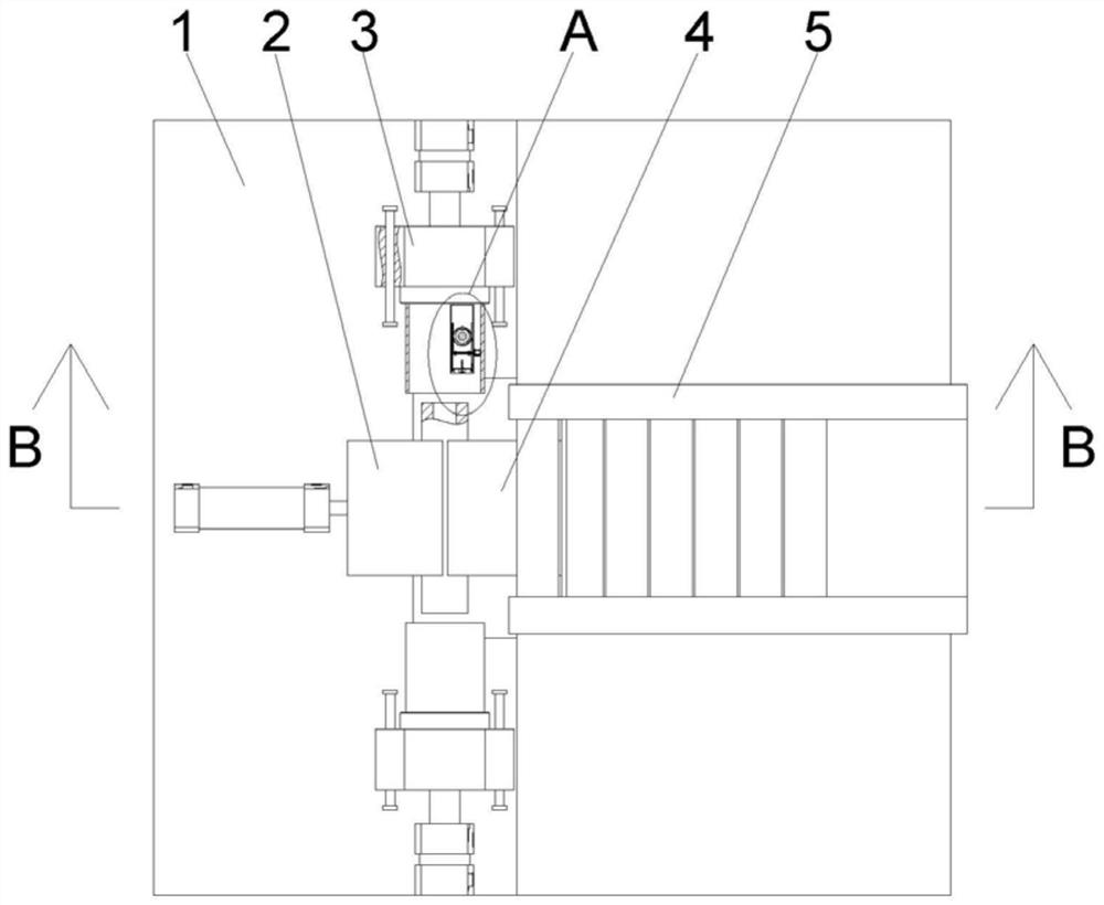
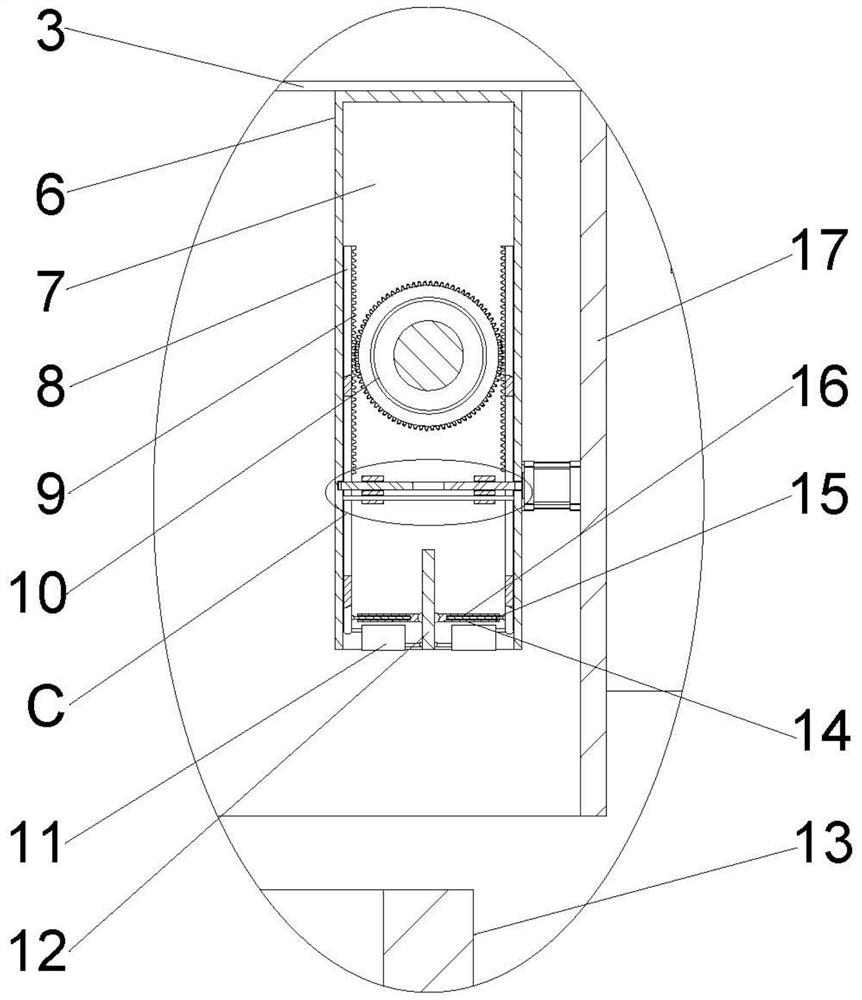
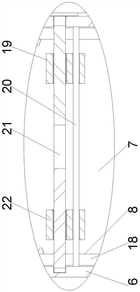
[0028] Such as figure 1 and figure 2 In the described embodiment, a fully automatic chamfering machine for pipes includes a frame 1, on which a fixing device and a chamfering device are installed, and the chamfering device includes rotational power symmetrically distributed on both sides of the front and back of the fixing device Head 3, the rotating power head 3 is slidingly connected with the frame 1, the rotating surface of the rotating power head 3 is fixed with a fixed block 6, and the fixed block 6 is provided with a fixed block groove 7 on one side close to the fixing device, and the fixed block groove 7 A dividing plate 12 is fixed at the middle position of the opening, and a cutter 11 is arranged at the opening of the fixed block groove 7, and the cutters 11 are symmetrically distributed on both sides of the dividing plate 12, and on...


PUM


Abstract

The invention discloses a pipe automatic chamfering machine. It includes a frame on which a fixing device and a chamfering device are installed. The chamfering device includes rotating power heads symmetrically distributed on the front and rear sides of the fixing device. The rotating power head is slidingly connected with the frame. A fixed block is fixed, a fixed block groove is arranged on the side of the fixed block close to the fixing device, a partition is fixed at the middle position of the opening of the fixed block groove, and knives are arranged at the opening of the fixed block groove, and the knives are symmetrically distributed on the partition On both sides of the plate, one side of the tool is installed on the partition plate and connected to it in rotation, a sliding plate matching the number of knives is slidably connected to the side wall of the groove of the fixed block, and the other side of the tool is installed on the Sliding plate and its rotational connection. The beneficial effect of the invention is that: the inner chamfer can be processed and the outer chamfer can be processed; the chamfer processing at any angle is realized.

Description

technical field [0001] The invention relates to the related technical field of chamfering machines, in particular to an automatic pipe chamfering machine. Background technique [0002] The chamfering machine is a small precision machine tool that is specially used for chamfering of mold manufacturing, hardware machinery, machine tool manufacturing, hydraulic parts, valve manufacturing, textile machinery, and deburring of milling and planing products. The use of fast machine chamfering is the development trend of the machinery industry. It overcomes the processing shortcomings of existing mechanical and electric tools, and has the advantages of convenience, speed and accuracy. It is the best choice for chamfering metal objects at present. According to the needs of chamfering, it can be divided into straight line chamfering and curved chamfering. [0003] The chamfering machine is a special tool for chamfering and beveling the front end of the pipe or plate. The chamfering m...

Claims


Application Information

Patent Timeline
Patent Type & Authority Patents(China)
IPC IPC(8): B23D79/00B23Q11/08B23Q7/00
CPCB23D79/00B23Q11/08B23Q7/00
Inventor 郭洪明
Owner HANGZHOU PANASIA SANITARY WARE
Learn More