
Mechanical equipment for welding connecting rod

A technology of mechanical equipment and connecting rod, applied in the field of connecting rod welding, can solve the problems of reducing the life of the welding head, reducing the toughness of the welding joint, and cooling the welding part, and achieves the effects of improving the welding efficiency, preventing the reduction of the toughness and softening the flame.

Active Publication Date: 2021-06-25
浙江德清精艺汽配有限公司
View PDF10 Cites 0 Cited by
  • Summary
  • Abstract
  • Description
  • Claims
  • Application Information

AI Technical Summary

Problems solved by technology

[0002] The existing mechanical equipment for partially welding connecting rods tends to cause the temperature of the welding part to be too high when welding the connecting rods, resulting in an overheated coarse-grained structure, which reduces the toughness of the welded joints, and the continuous high temperature makes the temperature of the welded joints also decrease. Continuously increasing, it is easy to reduce the life of the welding head, such as the patent with the publication number CN109352221A, in which the welding head is mainly welded along the circumference of the connecting rod, which has a high degree of automation, but this method cannot cool down the welding part , so that the temperature of the welding part is too high, resulting in an overheated coarse-grained structure, which reduces the toughness of the welded joint

Method used


Image

  • Mechanical equipment for welding connecting rod
  • Mechanical equipment for welding connecting rod
  • Mechanical equipment for welding connecting rod

Examples


Embodiment 1

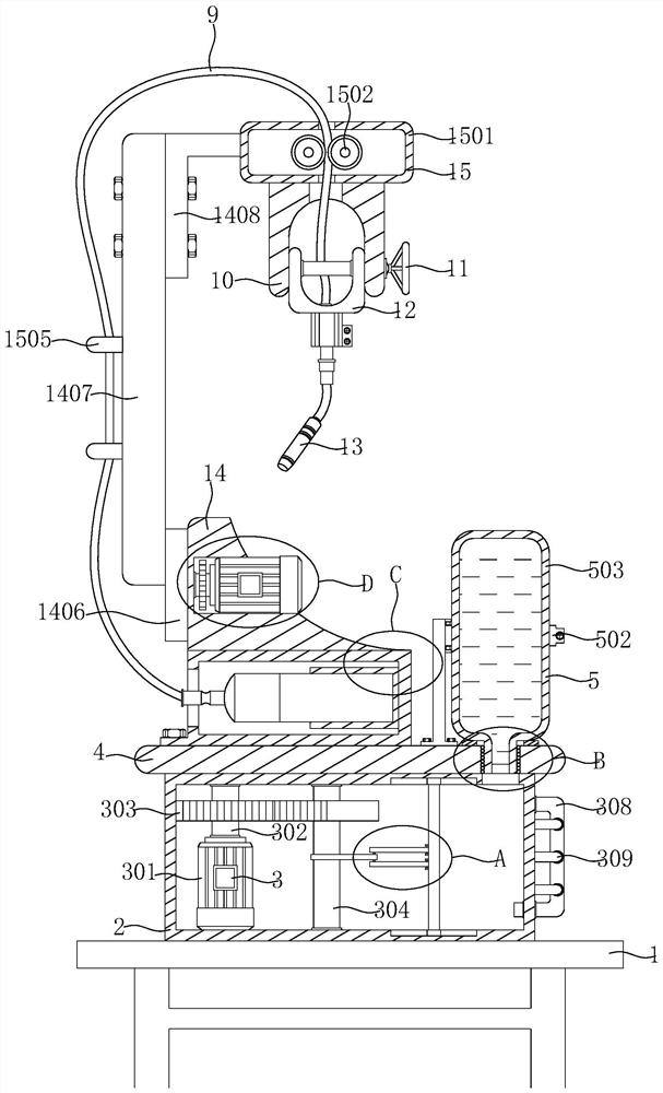
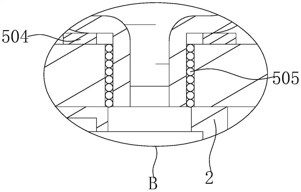
[0028] see Figure 1-8, the present invention provides a technical solution: a mechanical device for welding connecting rods, including a working platform 1, a working box 2 is fixedly installed on the top outer surface of the working platform 1, and a cooling mechanism 3 is arranged inside the working box 2, The top outer surface of the work box 2 is provided with a load-bearing plate 4, the water-adding mechanism 5 is arranged on the load-bearing plate 4, the top outer surface of the load-bearing plate 4 is fixedly installed with a protective cover 6, and the inner wall of one side of the protective cover 6 is fixedly connected with a fixed sleeve 7. The inside of the fixed sleeve 7 is provided with a MAPP bottle 8, one end of the MAPP bottle 8 is fixedly connected with an explosion-proof hose 9 and communicates with the inside, the top of the working platform 1 is provided with a first arcuate plate 10, and the first arcuate plate 10 is provided with a There is an opening, ...

Embodiment 2

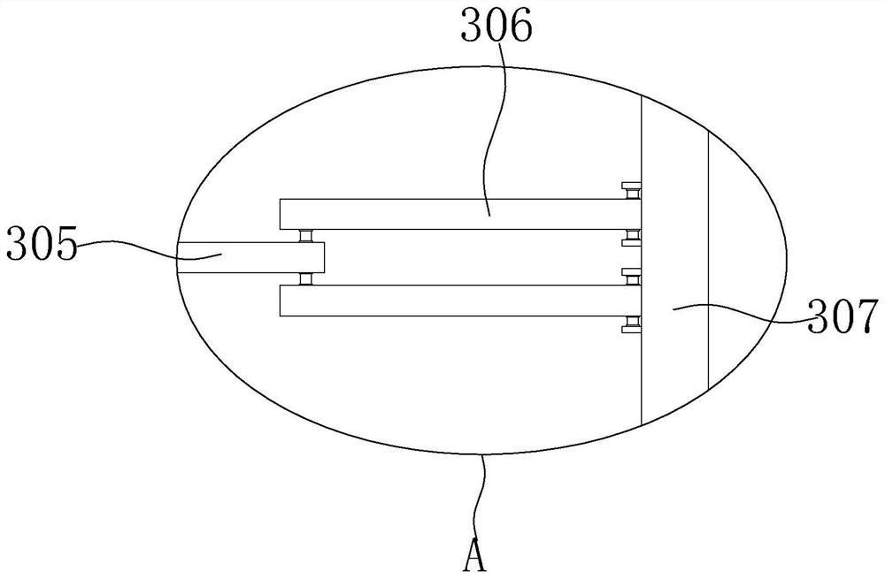
[0030] see Figure 1-8 , on the basis of Embodiment 1, the cooling mechanism 3 includes a first motor 301, a coarse rotating rod 302, a first driving gear 303, a long rotating rod 304, an eccentric wheel 305, a hinged frame 306, a sealing plate 307, and a U-shaped tube 308 And the L-shaped pipe 309, the inner top of the working box 2 is rotatably equipped with a coarse rotating rod 302, the inner bottom of the working box 2 is fixedly installed with a first motor 301, and the output shaft of the first motor 301 is connected with the coarse rotating rod 302 through a coupling. One end of the thick rotating rod 302 is fixedly connected with the first driving gear 303 on the fixed sleeve, and the inner bottom of the working box 2 is rotatably equipped with a long rotating rod 304, and the fixed sleeve on the long rotating rod 304 is provided with the first group of incomplete gears and The eccentric wheel 305, the first set of incomplete gears mesh with the first driving gear 303...


PUM


Abstract

The invention discloses mechanical equipment for welding a connecting rod, and relates to the technical field of connecting rod welding. The mechanical equipment for welding the connecting rod comprises a working platform, a working box is fixedly installed on the outer surface of the top of the working platform, a cooling mechanism is arranged in the working box, a bearing plate is arranged on the outer surface of the top of the working box, and a water adding mechanism is arranged on the bearing plate. According to the mechanical equipment for welding the connecting rod, through cooperative use of a first motor, a thick rotating rod, a first driving gear, a long rotating rod, an eccentric wheel, a hinge frame, a sealing plate, a U-shaped pipe and an L-shaped pipe, one machine can achieve multiple purposes, the welding position can be cooled while the height of a welding joint is automatically adjusted, the phenomenon that overheated coarse grain structures are generated due to the fact that the welding temperature is too high is avoided, electric sparks are reduced, the toughness of the welding joint is effectively prevented from being reduced, the welding joint can keep a certain temperature, and the service life of the welding joint is prolonged.

Description

technical field [0001] The invention relates to the technical field of connecting rod welding, in particular to a mechanical device for welding connecting rods. Background technique [0002] The existing mechanical equipment for partially welding connecting rods tends to cause the temperature of the welding part to be too high when welding the connecting rods, resulting in an overheated coarse-grained structure, which reduces the toughness of the welded joints, and the continuous high temperature makes the temperature of the welded joints also decrease. Continuously increasing, it is easy to reduce the life of the welding head, such as the patent with the publication number CN109352221A, in which the welding head is mainly welded along the circumference of the connecting rod, which has a high degree of automation, but this method cannot cool down the welding part , so that the temperature of the welding part is too high, resulting in an overheated coarse-grained structure, t...

Claims


Application Information

Patent Timeline
Patent Type & Authority Applications(China)
IPC IPC(8): B23K37/00B23K37/02B23K5/00B23K5/22B23K5/24
CPCB23K37/00B23K37/003B23K37/0247B23K5/00B23K5/22B23K5/24
Inventor 徐云昌
Owner 浙江德清精艺汽配有限公司
Learn More