
Device for monitoring pile foundation scouring depth in real time and monitoring method thereof

A technology for scouring depth and real-time monitoring, which is applied to measurement devices, circuit devices, battery circuit devices, etc., can solve the problems of complex overall structure, result error, danger, etc. Effect

Active Publication Date: 2021-06-25
OCEAN UNIV OF CHINA
View PDF14 Cites 2 Cited by
  • Summary
  • Abstract
  • Description
  • Claims
  • Application Information

AI Technical Summary

Problems solved by technology

Existing research methods and detection methods do not have real-time monitoring effects, underwater operations are difficult and dangerous, there is no complete set of monitoring system equipment, and there are large errors in the results
[0004] In order to solve the above problems, relevant patents have been disclosed, such as Chinese patent publications CN 106052604 A, CN109239700 A, CN 109610528 A, CN 110398210 A, CN 110470447 A, CN 111561974 A, CN112082527 A, etc., all of which provide information for the study of scour depth. At the same time, He Shaoyang, Research on the identification method of scour depth of bridge pier based on time-varying modal parameters [D], Harbin Institute of Technology, 2016 also published research on scour depth, but the above-mentioned technology still has many deficiencies, such as the overall The structure is complex, it is not easy to implement, there is no real-time monitoring effect, and there is no complete set of monitoring system equipment and other defects

Method used


Image

  • Device for monitoring pile foundation scouring depth in real time and monitoring method thereof
  • Device for monitoring pile foundation scouring depth in real time and monitoring method thereof
  • Device for monitoring pile foundation scouring depth in real time and monitoring method thereof

Examples


Embodiment Construction

[0046] The present invention will be further described below in conjunction with the accompanying drawings and embodiments.

[0047] The structures, proportions, sizes, etc. shown in the drawings in this specification are only used to cooperate with the contents disclosed in the specification for the understanding and reading of those who are familiar with the technology, and are not intended to limit the conditions for the implementation of the present invention. , therefore does not have technical substantive significance, any structural modification, proportional relationship change or size adjustment, without affecting the effect that the present invention can produce and the purpose that can be achieved, should still fall within the scope of the present invention. within the scope of the technical content. At the same time, the terms such as "up", "down", "left", "right", "middle" and "one" quoted in this specification are only for the convenience of description and clari...


PUM


Abstract

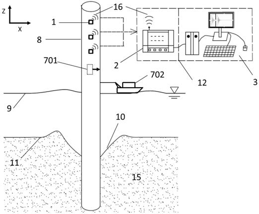
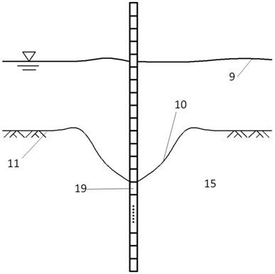
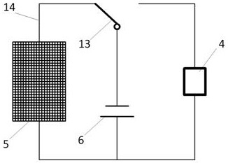
The invention discloses equipment for monitoring the scouring depth of a pile foundation in real time and a monitoring method of the equipment. The monitoring equipment comprises a sensor group, a data acquisition instrument, data processing equipment, a solar panel, a storage battery and excitation equipment. In specific implementation, the method comprises the steps that excitation is applied to a pile foundation through excitation equipment, and after actual measurement modes of the pile foundation are obtained through induction, collection and data processing equipment, and a cross model cross mode equation is constructed in combination with corresponding finite element numerical model modes; and the soil body unit damage number is identified through the unit rigidity correction coefficient alpha n of the equation, and further the scouring depth around the pile foundation is acquired. The purpose of monitoring the pile foundation scouring depth on water can be achieved, meanwhile, the scouring depth change situation in the whole service life after the pile foundation is put into production can be monitored in real time, the problem that the scouring depth is difficult to monitor through traditional manual diving is solved, and the potential risks caused by the fact that the pile foundation scouring depth is uncertain are avoided; besides, the method has the advantages of good operability, labor saving, strong adaptability and the like.

Description

technical field [0001] The invention relates to the technical field of pile foundation stability analysis and disaster prevention and mitigation, in particular to a device and a monitoring method for real-time monitoring of the scour depth of pile foundations. Background technique [0002] The 21st century is the century of the ocean. The construction of offshore wind farms is an important part of the utilization and development of marine resources. Large-diameter tubular piles are the main form of offshore wind turbine foundations due to their simple construction process and low cost. Facing the harsh marine environment and complex seabed soil properties, the monopile foundation will inevitably be scoured by the wave currents on the soil around the pile foundation during the service period, forming scour pits. The soil around the pile foundation reduces the constraining effect of the single pile, which affects the bearing stability of the foundation, and the mode of the pil...

Claims


Application Information

Patent Timeline
Patent Type & Authority Applications(China)
IPC IPC(8): G01B17/00G06F30/20G08C17/02H02J7/35E02D33/00E02D27/12
CPCG01B17/00G06F30/20G08C17/02H02J7/35E02D33/00E02D27/12Y02E10/727
Inventor 陈旭光卢光坤杜文博解安琪陈常龙牛小东
Owner OCEAN UNIV OF CHINA
Learn More