Time-triggered passive optical bus and implementation method thereof

A technology of time triggering and implementation method, which is applied in the direction of electromagnetic wave transmission system, electrical components, transmission system, etc., can solve the problems of cumbersome configuration, achieve high link rate, increase status monitoring, and improve the overall anti-interference ability

Active Publication Date: 2021-06-25
UNIV OF ELECTRONICS SCI & TECH OF CHINA +1
View PDF10 Cites 0 Cited by
  • Summary
  • Abstract
  • Description
  • Claims
  • Application Information

AI Technical Summary

Problems solved by technology

The configuration of Configuration Data is cumbersome and needs to be configured one by one

Method used


Image

  • Time-triggered passive optical bus and implementation method thereof
  • Time-triggered passive optical bus and implementation method thereof
  • Time-triggered passive optical bus and implementation method thereof

Examples


Embodiment 1

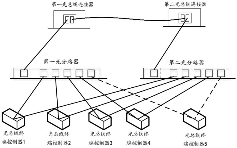
[0057] A time-triggered passive optical bus structure in this embodiment such as figure 1 As shown, it includes a first optical bus connector, a second optical bus connector, a plurality of optical bus terminal controllers, a first optical splitter and a second optical splitter; each optical bus terminal controller has two port, the two ports are respectively connected to the first optical splitter and the second optical splitter; each optical bus connector has 2 optical fiber ports, and one port of the first optical bus connector is connected to the first optical splitter , one port of the second optical bus connector is connected to the second optical splitter, and the other port of the first optical bus connector is connected to the other port of the second optical bus connector.

[0058] The optical bus connectors are all provided with an optical bus connector state control unit, and the optical bus terminal controllers are all provided with an optical bus terminal control...

Embodiment 2

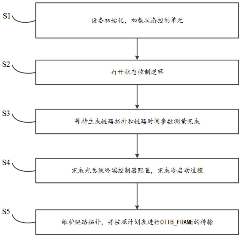
[0061] A method for implementing a time-triggered passive optical bus, which can be applied to a time-triggered passive optical bus in Embodiment 1, the bus includes two optical bus connectors, multiple optical bus terminal controllers, and two optical shunts The optical bus connectors are all provided with an optical bus connector state control unit, and the optical bus terminal controllers are all provided with an optical bus terminal controller state control unit. The two optical bus connectors are denoted as the first optical bus connector and the second optical bus connector. Two optical bus connectors, two optical splitters are recorded as the first optical splitter and the second optical splitter, and its work flow chart is as follows figure 2 The following steps are shown:

[0062] S1: Initialize the device, load the optical bus connector state control unit and the optical bus terminal controller state control unit;

[0063] S2: Open the state control logic of the st...

Embodiment 3

[0068] refer to Figure 5 , this embodiment is based on the method flow of Embodiment 2, wherein the state control logic of the optical bus connector state control unit includes the following steps,

[0069] Step 010: By default, the first optical bus connector is used to send configuration data, which is sent to each node through the first optical splitter, and the second optical bus connector forwards the configuration data from the first optical bus connector to the second optical Splitter, and complete the measurement of the link delay information of the second optical splitter, set the local member vector to 0, initialize the local clock of the device to 0, use a local clock globally, and use the Micro Clock as the minimum clock for the local clock cycle;

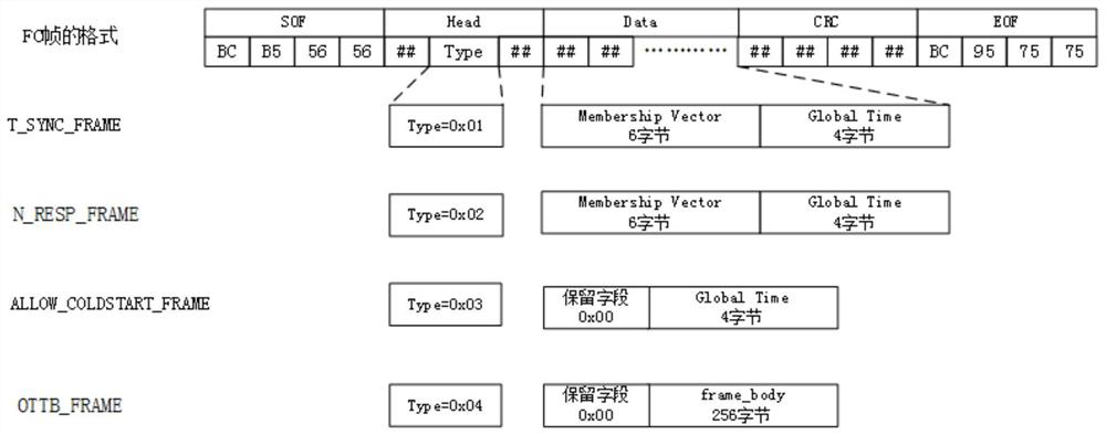
[0070] Step 020: The first optical bus connector cyclically sends T_SYNC_FRAME frames to the connected first optical splitter and second optical bus connector, and the two optical bus connectors respectively record th...


PUM


Abstract

The invention discloses a time-triggered passive optical bus and an implementation method thereof, relates to the field of time-triggered buses based on light, and aims to provide a bus which is light in weight and avoids collision in a cold start stage. The bus comprises a first optical bus connector, a second optical bus connector, a plurality of optical bus terminal controllers, a first optical splitter and a second optical splitter; each optical bus terminal controller is provided with two ports, and the two ports are respectively connected to the two optical splitters; each optical bus connector is provided with two optical fiber ports, one port of the first optical bus connector is connected with the first optical branching device, one port of the second optical bus connector is connected with the second optical branching device, and the other port of the first optical bus connector is connected with the other port of the second optical bus connector. Meanwhile, the invention also provides a corresponding implementation method, the body weight and the wiring difficulty are reduced, the anti-jamming capability is high, and sending collision in the cold start stage is avoided.

Description

technical field [0001] The invention relates to the field of time-triggered buses based on light, in particular to a time-triggered passive optical bus and its realization method. Background technique [0002] Optical fiber is the abbreviation of optical fiber. Optical fiber communication is a communication method in which light waves are used as information carriers and optical fibers are used as transmission media. In principle, the basic material elements that constitute optical fiber communication are optical fibers, light sources and photodetectors. Optical fiber communication is a communication method that uses light waves as a carrier and optical fiber as a transmission medium to transmit information from one place to another. It is called "wired" optical communication. Nowadays, optical fiber has become the main transmission mode in the world communication because of its wide transmission frequency bandwidth, high anti-interference and low signal attenuation, which...

Claims


Application Information

Patent Timeline
Patent Type & Authority Applications(China)
IPC IPC(8): H04B10/079
CPCH04B10/0795
Inventor 彭逸飞涂晓东牛萌李港刘坤谢军张超
Owner UNIV OF ELECTRONICS SCI & TECH OF CHINA
Why Eureka
Try Eureka