
Anesthetic equipment capable of automatically switching anesthetic gas and oxygen

An automatic switching, anesthetic gas technology, applied in breathing masks, respirators, etc., can solve the problems of emergency rescue, deepening of anesthesia, and aggravation of respiratory arrest for patients with unfavorable respiratory arrest, reducing rescue steps and having a simple structure. , easy to achieve effect

Pending Publication Date: 2021-06-29
THE FIRST AFFILIATED HOSPITAL OF HENAN UNIV OF SCI & TECH
View PDF0 Cites 0 Cited by
  • Summary
  • Abstract
  • Description
  • Claims
  • Application Information

AI Technical Summary

Problems solved by technology

On the one hand, this process is cumbersome, involving operations such as changing the mask, switching on and off the ventilator and anesthesia machine, and on the other hand, it requires the joint implementation of multiple people, which is not conducive to the emergency rescue of patients with respiratory arrest during inhalation anesthesia
Even in the process of partial anesthesia, the medical staff continued to deliver anesthetics through the anesthesia mask because they failed to detect the patient's respiratory arrest in time, which further aggravated the sudden respiratory arrest and further deepened the patient's anesthesia depth, resulting in unnecessary medical treatment. ACCIDENT

Method used


Image

  • Anesthetic equipment capable of automatically switching anesthetic gas and oxygen
  • Anesthetic equipment capable of automatically switching anesthetic gas and oxygen
  • Anesthetic equipment capable of automatically switching anesthetic gas and oxygen

Examples


Embodiment Construction

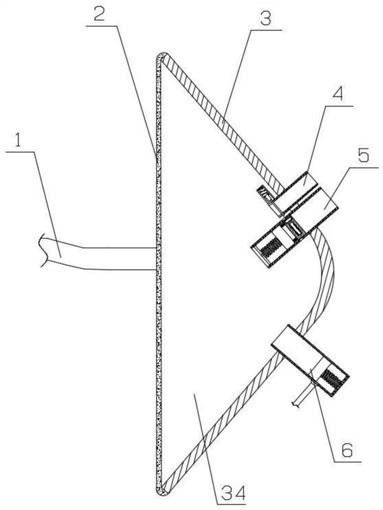
[0028] Such as figure 1 As shown, the main body of this embodiment is a breathing mask 3, and the breathing mask 3 is used to form a breathing zone 34 between the back of the patient's face and the patient's nose and mouth. In order to ensure the sealing of the breathing area 34 and prevent the anesthesia gas passing into the breathing area 34 and the components of the anesthetic gas in the exhalation of the patient from escaping and diffusing from the breathing area 34, the breathing mask 3 in this embodiment is also provided with an elastic fixing belt 1 and sealing strip 2. The breathing mask 3 is buckled and fixed on the patient's head through the elastic fixing belt 1 to avoid falling off, and the sealing strip 2 is used to maintain the isolation state of the breathing zone 34 from the outside atmosphere.

[0029]An oxygen tube 4 , an anesthesia tube 5 and a waste gas tube 6 inserted into the breathing zone 34 are sequentially arranged on the breathing mask 3 from top to...


PUM


Abstract

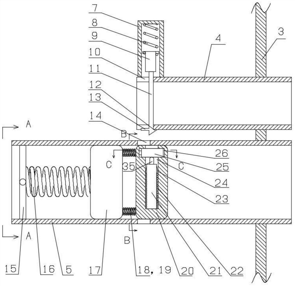
Anesthetic equipment capable of automatically switching anesthetic gas and oxygen comprises a respiratory mask; an openable and normally closed end cover is arranged at the front end of an oxygen pipe; an anesthetic piston valve is arranged at the front end of an anesthetic gas pipe; a waste gas piston valve is arranged at the front end of a waste gas pipe; the anesthetic piston valve and the waste gas piston valve are controlled to be opened by an inspiration process and an expiration process of a patient, so that the anesthetic gas pipe communicates with a respiratory region when the patient inhales, and the waste gas pipe communicates with the respiratory region when the patient exhales; the tail end of the anesthetic gas pipe is connected with an anesthetic tank through a pressure pump; a switching mechanism capable of cooperating with the end cover is further arranged on the side, facing the pressure pump, of the anesthetic piston valve; and the switching mechanism is used for being triggered by the continuous pressurization effect of the pressure pump after respiratory arrest of the patient so as to isolate the communication between the anesthetic gas pipe and the respiratory region and open the end cover to make the oxygen pipe communicate with the respiratory region. According to the anesthetic equipment, in the inhalation type anesthesia process, supply of anesthetic / oxygen is switched once the respiratory arrest occurs, so that precious time for rescuing a patient is saved to avoid that an accident is further aggravated.

Description

technical field [0001] The invention relates to the field of medical anesthesia equipment, in particular to an anesthesia equipment for automatic switching of anesthesia gas and oxygen. Background technique [0002] Inhalation anesthesia is a general anesthesia method that directs the inhalation of anesthetics or anesthetic gases into the blood from the respiratory system and inhibits the central nervous system. In the history of anesthesia, inhalation anesthesia is the earliest anesthesia method. The clinical manifestations after anesthesia are loss of consciousness, loss of general pain sensation, amnesia, reflex inhibition and skeletal muscle relaxation. The degree of inhibition of the anesthetic effect on the central nervous system is related to the drug concentration in the blood, and can be controlled and adjusted, and this inhibition is completely reversible. When the drug is metabolized or excreted from the body, the patient's consciousness and various reflections gr...

Claims


Application Information

Patent Timeline
IPC IPC(8): A61M16/01A61M16/00A61M16/06A61M16/08A61M16/20
CPCA61M16/00A61M16/01A61M16/06A61M16/08A61M16/20A61M16/208A61M16/022
Inventor 何艳辉尚霄张益锋
Owner THE FIRST AFFILIATED HOSPITAL OF HENAN UNIV OF SCI & TECH
Learn More