Polishing device for battery protection shell of reconnaissance robot

A kind of protective shell and robot technology, which is applied in the direction of grinding drive device, grinding/polishing safety device, device for fixing grinding wheel, etc. The effect of dead angle, ensuring efficiency and improving flexibility

Inactive Publication Date: 2021-06-29
章余
View PDF9 Cites 5 Cited by
  • Summary
  • Abstract
  • Description
  • Claims
  • Application Information

AI Technical Summary

Problems solved by technology

[0005] The purpose of the present invention is to solve the shortcomings in the prior art that only the cylindrical protective shell can be polished in the process of grinding the protective shell, and the rectangular protective shell cannot be polished, which reduces the efficiency of grinding. And proposed a reconnaissance robot battery protective shell grinding device

Method used


Image

  • Polishing device for battery protection shell of reconnaissance robot
  • Polishing device for battery protection shell of reconnaissance robot
  • Polishing device for battery protection shell of reconnaissance robot

Examples


Embodiment 1

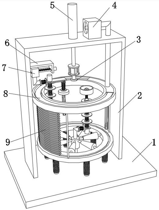
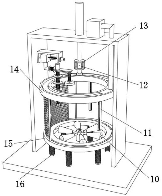
[0036] A reconnaissance robot battery protective shell grinding device, such as Figure 1-5 As shown, it includes a base 1 and a supporting mechanism. The outer wall of the top of the base 1 is fixed with a support frame 2 by bolts, and the inner wall of one side of the support frame 2 is fixed with an electric screw slide rail 6 by bolts. The electric screw slide rail 6 The output end is slidably connected with a slider 7, the outer wall on one side of the slider 7 is fixed with a telescopic frame 20 by bolts, the inner wall on one side of the slider 7 and the inner wall on the side of the telescopic frame 20 are clamped with the same spring 4 31, the top outer wall of the telescopic frame-20 is fixed with a grinding motor-21 by bolts, the bottom outer wall of the telescopic frame-20 is rotatably connected with a mounting column-28, and the output end of the polishing motor-21 is connected to the Described mounting post-28 top inner wall, described mounting post-28 circumfere...

Embodiment 2

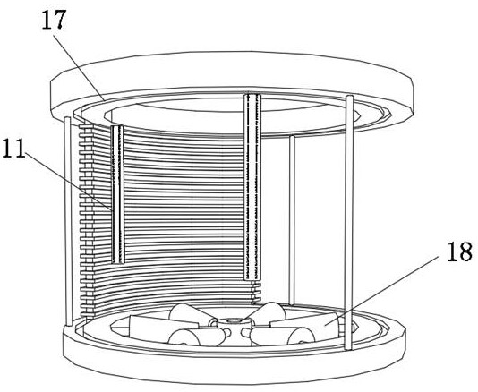
[0045] A reconnaissance robot battery protective shell grinding device, such as Figure 7 As shown, in order to facilitate the grinding of the rectangular protective casing; this embodiment makes the following improvements on the basis of Embodiment 1: the outer wall of the top of the connecting frame 10 is connected to the rotating seat 41 through bearing rotation; at the same time, due to the shape of the battery protective casing Be cylindrical, also may be rectangular, by being provided with telescopic frame 120 and spring 4 31 can when grinding wheel 129 is polished to the prismatic cylindrical protective shell outer wall, make grinding wheel 129 circumference outer walls can be better ground and the surface of the prismatic cylindrical protective shell to ensure the effect of grinding, while the telescopic frame 2 33 and the spring 5 35 have the same effect, and the rotating seat 41 can be used to place the rectangular protective shell to make crimping The motor 12 can d...


PUM


Abstract

The invention discloses a polishing device for a battery protection shell of a reconnaissance robot, and relates to the technical field of battery protection shell polishing devices. The polishing device is used for conveniently polishing battery protection shells of different shapes. The polishing device specifically comprises a base and a supporting mechanism; a supporting frame is fixed to the outer wall of the top of the base through bolts, an electric lead screw sliding rail is fixed to the inner wall of one side of the supporting frame through bolts, a sliding block is slidably connected to the output end of the electric lead screw sliding rail, and a first telescopic frame is fixed to the outer wall of one side of the sliding block through bolts; and the same fourth spring is clamped to the inner wall of one side of the sliding block and the inner wall of one side of the first telescopic frame, a first polishing motor is fixed to the outer wall of the top of the first telescopic frame through bolts, and a first mounting column is rotationally connected to the outer wall of the bottom of the first telescopic frame. By arranging the electric lead screw sliding rail, the sliding block can be driven to move in the horizontal direction, and the supporting mechanism can be used for containing a cylindrical protection shell.

Description

technical field [0001] The invention relates to the technical field of grinding devices for battery protective casings, in particular to a grinding device for battery protective casings of reconnaissance robots. Background technique [0002] Reconnaissance robots have powerful field reconnaissance capabilities, can pass through various complex terrains, and can work in harsh environments, replacing humans to perform some dangerous tasks, thereby completing hostile information reconnaissance tasks. The battery is powered, and the battery needs to be protected by a protective shell, which needs to be polished during the production process of the protective shell. [0003] After searching, the Chinese patent application number is CN202010272670.4, which discloses a crawler-type reconnaissance robot battery protective shell grinding device, including a bottom plate and legs, and the legs are symmetrically arranged at the bottom of the bottom plate. A vertical frame is arranged ...

Claims


Application Information

Patent Timeline
Patent Type & Authority Applications(China)
IPC IPC(8): B24B5/36B24B5/35B24B19/00B24B27/00B24B41/02B24B47/22B24B47/12B24B41/04B24B55/06B24B45/00
CPCB24B5/36B24B5/35B24B19/00B24B27/0076B24B41/02B24B47/22B24B47/12B24B41/04B24B55/06B24B45/003
Inventor 章余
Owner 章余
Why Eureka
Try Eureka