Supercharge Your Innovation With Domain-Expert AI Agents!

Building environment-friendly drainage system and drainage method

A drainage system and environmental protection technology, applied in construction, chemical instruments and methods, biological water/sewage treatment, etc., can solve problems such as odor, impact on surrounding environment, inconvenience, etc., to reduce scale generation, simplify treatment steps, and high effect

Inactive Publication Date: 2021-06-29
贵州工业职业技术学院
View PDF0 Cites 0 Cited by
  • Summary
  • Abstract
  • Description
  • Claims
  • Application Information

AI Technical Summary

Problems solved by technology

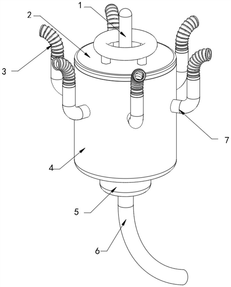
The general term for all levels of drainage ditches (pipes) and buildings used for waterlogging, waterlogging, and salt prevention. The excess water in the drainage area first flows into the field drainage regulation network, and then is discharged to the discharge area by the drainage sluice or the pumping station after passing through the drainage ditches at all levels or through the lake. Field, especially for the drainage system in the construction field, the drainage system of the existing building body is that the tap water directly enters the drainage pipe network after use. In the process of domestic sewage discharge, the domestic sewage inside the building is doped with a large amount of impurities. After each kind of domestic sewage is discharged into the drainage pipe network, different impurities will produce different reactions together, which will bring inconvenience to the sewage treatment process. In addition, when tap water enters the drainage pipe, scale will be generated inside the pipe , provides a growth environment for bacteria to breed, produces peculiar smell, and affects the surrounding environment. Therefore, in order to solve such problems, we propose a building environmental protection drainage system and drainage method

Method used


Image

  • Building environment-friendly drainage system and drainage method
  • Building environment-friendly drainage system and drainage method
  • Building environment-friendly drainage system and drainage method

Examples


Embodiment Construction

[0028] The following will clearly and completely describe the technical solutions in the embodiments of the present invention with reference to the accompanying drawings in the embodiments of the present invention. Obviously, the described embodiments are only some, not all, embodiments of the present invention.

[0029] In describing the present invention, it should be understood that the terms "upper", "lower", "front", "rear", "left", "right", "top", "bottom", "inner", " The orientation or positional relationship indicated by "outside", etc. is based on the orientation or positional relationship shown in the drawings, and is only for the convenience of describing the present invention and simplifying the description, rather than indicating or implying that the referred device or element must have a specific orientation, so as to Specific orientation configurations and operations, therefore, are not to be construed as limitations on the invention.

[0030] refer to Figure ...


PUM


Abstract

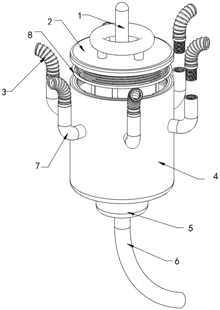
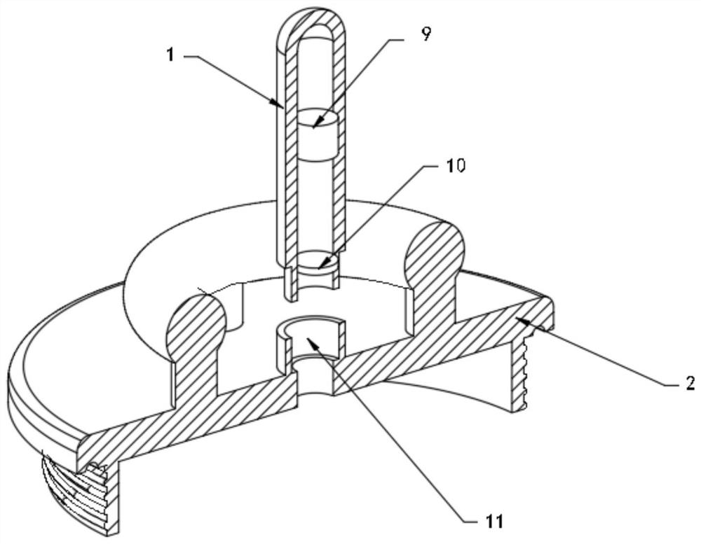
The invention discloses a building environment-friendly drainage system and a drainage method. The drainage system comprises a main body cylinder, the upper end of the main body cylinder is in threaded connection with a sealing end cover, first connecting ends are evenly distributed and fixedly installed on the circumferential outer wall of the main body cylinder, a reducing pipe is fixedly installed in the center of the lower surface of the main body cylinder, a water outlet pipe is fixedly installed in the center of the lower surface of the reducing pipe, a connecting ring frame is fixedly installed at the bottom end in the reducing pipe, an installation base table is rotatably installed in the center of the connecting ring frame, a center connecting cylinder is fixedly installed in the center of the upper surface of the installation base table, turbine fan blades are evenly and fixedly installed on the circumferential outer wall of the installation base table, and a horizontally-distributed filtering plate is arranged in the main body cylinder. In the using process, sewage is subjected to primary treatment through biodegradation and then flows into the drainage system, the treatment efficiency is high, and in the treatment process, the problems of bacterium breeding and peculiar smell generation can be solved.

Description

technical field [0001] The invention relates to the technical field of environmental protection drainage, in particular to a building environmental protection drainage system and a drainage method. Background technique [0002] The sewerage system refers to the overall combination of drainage collection, transportation, water quality treatment and discharge facilities in a certain way. The general term for all levels of drainage ditches (pipes) and buildings used for waterlogging, waterlogging, and salt prevention. It is mainly composed of field drainage regulation networks, drainage ditches at all levels, waterlogging lakes, drainage gates, pumping stations and The excess water in the drainage area first flows into the field drainage regulation network, and then is discharged to the discharge area by the drainage sluice or the pumping station after passing through the drainage ditches at all levels or through the lake. In the field, especially for the drainage system in th...

Claims


Application Information

Patent Timeline
IPC IPC(8): E03C1/12E03C1/122E03C1/126E03C1/264E03C1/302F03B13/00C02F9/14
CPCC02F1/001C02F3/34E03C1/12E03C1/122E03C1/126E03C1/264E03C1/302F03B13/00
Inventor 冉全
Owner 贵州工业职业技术学院
Features
  • R&D
  • Intellectual Property
  • Life Sciences
  • Materials
  • Tech Scout
  • Unparalleled Data Quality
  • Higher Quality Content
  • 60% Fewer Hallucinations
Learn More