
Liquid flow control sliding sleeve

A sliding sleeve and liquid flow technology, which is applied in wellbore/well components, earthwork drilling, sealing/isolation, etc., can solve the problem of easily scratching the metal seal of the reversing valve, reducing the service life of the electric pump, increasing operating costs, etc. problems, to achieve the effects of less risk of running liquid erosion, lower operating costs, and reduced workload

Active Publication Date: 2021-06-29
成都叁能锐达能源科技有限公司
View PDF10 Cites 0 Cited by
  • Summary
  • Abstract
  • Description
  • Claims
  • Application Information

AI Technical Summary

Problems solved by technology

[0003] At present, in the field of oil well exploitation, electric submersible pump wells are widely used in oil field production practice, but when complex well conditions or other objective factors cause electric When the pump unit stops running, impurities or sand particles in the pipe string will be deposited on the check valve under the action of gravity; when the amount of deposited sand accumulates to a certain extent, the check valve will be completely buried, making it difficult or even impossible to start the pump again. As a result, the oil well is shut down, causing workover operations and increasing operating costs
[0004]A lot of researches have been done on this problem in China, but the existing automatic reversing valves still have the following problems: 1. The valve directly controls the two working states of separation and closing , although the operating principle is very simple, but the phenomenon of erosion and liquid leakage is serious; 2. For fluid resistance, the existing reversing valve is greatly affected by the spring force and flow; 3. From the perspective of sealing, the existing The metal seal of the reversing valve is easy to scratch, and the rectangular seal is often used, which has a large sliding resistance; and the surface of the seal is polished, and the hardness is not enough, so it is easy to scratch and cause the seal to fail; 4. In the well of the self-spraying electric pump , the fluid will directly pass through the electric pump, which will not only increase the production flow resistance, but also erode and wear the electric pump, which will greatly reduce the service life of the electric pump; The phenomenon that causes the stuck pump

Method used


Image

  • Liquid flow control sliding sleeve
  • Liquid flow control sliding sleeve
  • Liquid flow control sliding sleeve

Examples


Embodiment 1

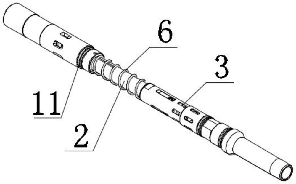
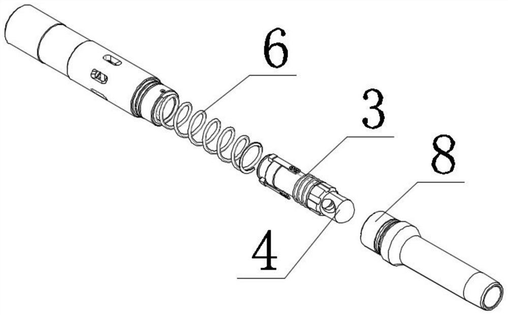
[0032] Such as Figure 1 to Figure 7 As shown, a fluid flow control sliding sleeve provided by a preferred embodiment of the present invention includes a central tube 2, and the upper part of the central tube 2 is slidably connected to an external pipe through a sliding sleeve body 1, and the sliding sleeve body 1 is connected to an external pipeline. The pipes are fixedly connected; the upper part of the central pipe 2 is provided with an annular pipe opening 9, and a sealing member 5 is provided at the connection between the annular pipe opening 9 and the central pipe 2; an oil outlet pipe 10 is set inside the central pipe 2; The outer middle part of the central tube 2 is wound with a second return spring 6, the bottom of the second return spring 6 is fixedly connected with the central tube 2, and the top of the second return spring 6 is fixedly connected with the sliding sleeve body 1; the central tube 2 The bottom of the center tube 2 is fixedly connected with a central ch...

Embodiment 2

[0040] In this embodiment, on the basis of Embodiment 1, the anchoring device 7 is replaced with a control ball, the central pipe 2 is provided with a central check valve control groove at the corresponding position, and the outer casing control tank is provided at the corresponding position on the inner wall of the external pipeline 11. groove.

[0041] At this time, the working principle of the present invention is: before starting the pump, the central check valve 4, the control ball and the center pipe 2 are locked together; The central pipe 2 goes upwards as a whole. After the annular pipe is closed, the control ball rolls into the control groove of the outer casing, and the central check valve 4 is released, and the fluid enters the oil pipe through the central check valve 4. When the pump is stopped, the central check valve 4 is released. The valve 4 is reset under the dual action of the first return spring 3 and the fluid pressure, the middle production channel is clos...

Embodiment 3

[0043] In this embodiment, on the basis of the first embodiment, the fluid flow control sleeve FCD (Flow Control Door) is applied to the electric submersible progressing cavity pump ESPCP (Electric Submersible Progressing Cavity Pum). ) and the electric submersible pump (ESP), the electric submersible screw pump combines the advantages of the electric submersible centrifugal pump and the screw pump, and the surface drive of the screw pump is directly driven by the motor through the reducer, and the sucker rod is removed , which solves the problems of sucker rod tripping, broken rod and eccentric wear; the working principle of this embodiment is similar to that of embodiment 1, but due to the working characteristics of the electric submersible screw pump, it is different from the When the electric submersible pump is reversed, the liquid flow direction is from bottom to top (inlet to outlet). This solution adds a check valve to solve the problem that when the electric submersibl...


PUM


Abstract

The invention discloses a liquid flow control sliding sleeve, and belongs to the field of petroleum underground exploitation. The liquid flow control sliding sleeve comprises a central pipe, wherein the upper part of the central pipe is in sliding connection with an external pipeline through a sliding sleeve body, and a sealing piece is arranged in the connecting position of an annular pipeline opening and the central pipe; an oil outlet pipeline sleeves the interior of the central pipe; the central pipe is reset through a second reset spring, a central check valve is fixedly connected to the bottom of the central pipe, and a valve seat which is matched with the central check valve is arranged below the central check valve; the central check valve is reset through a first reset spring; and an anchoring device is arranged on one side of the lower part of the central pipe, one end of the anchoring device is fixedly connected to the inner wall of the external pipeline, and the anchoring device is located above the first reset spring. The liquid flow control sliding sleeve has the advantages of low valve opening pressure, large fluid channel, small fluid resistance, small sliding resistance, high sand prevention capacity, excellent sand resistance and wear resistance, small liquid leakage erosion risk, high overall reliability and the like.

Description

technical field [0001] The invention belongs to the field of oil well mining, in particular to a liquid flow control sliding sleeve. Background technique [0002] The reversing valve is a directional control valve with more than two flow forms and more than two oil ports; it is a valve that realizes communication, cut-off and reversing of hydraulic oil flow, as well as pressure unloading and sequential action control; There are two kinds of rotary valve type and slide valve type; according to the number of working positions where the valve core stays in the valve body, it is divided into two positions, three positions, etc.; according to the number of oil circuits connected to the valve body, it is divided into Two-way, three-way, four-way and six-way, etc.; there are manual, motorized, electric, hydraulic, electro-hydraulic and other types of operating spool movement. [0003] At present, in the field of oil well mining, submersible electric pump wells are widely used in o...

Claims


Application Information

Patent Timeline
Patent Type & Authority Applications(China)
IPC IPC(8): E21B34/14
CPCE21B34/14
Inventor 张强郭志勋穆春峰邱前进
Owner 成都叁能锐达能源科技有限公司
Learn More