Controllable electric supercharging device for engine

A technology of electric supercharger and electric supercharger, which is applied in the direction of engine control, combustion engine, machine/engine, etc., can solve the problems of engine economy decline, efficiency decline, increase intake resistance, etc., and improve low-speed response , to ensure efficiency, to avoid the effect of aerodynamic lag

Inactive Publication Date: 2021-06-29
DONGFENG COMML VEHICLE CO LTD
View PDF5 Cites 0 Cited by
  • Summary
  • Abstract
  • Description
  • Claims
  • Application Information

AI Technical Summary

Problems solved by technology

[0005] Generally, turbocharged engines have insufficient boost pressure at low speeds due to insufficient exhaust gas capacity, which limits the increase in fuel injection volume, resulting in poor torque performance at low speeds, which is detrimental to the power performance of the car
[0006] Turbocharging cannot take into account both low-speed and high-speed performance at the same time. Reducing the turbocharger volute will improve the low-speed performance. However, in order to prevent the supercharger from overspeeding at high speeds, a part of the exhaust gas of the engine is bypassed by waste gas bypass, thereby losing Part of the exhaust gas energy, resulting in a decrease in efficiency
On the other hand, enlarging the supercharger volute improves high-rpm performance, but results in poorer efficiency and responsiveness at lower rpm
[0007] Slow engine response at low rpm due to turbocharger aerodynamic lag
[0008] At the same time, if only electric supercharging is used, although the supercharging pressure requirements of different working conditions of the engine are met, the energy of the exhaust gas of the engine cannot be utilized, which reduces the economical efficiency of the engine.
The existing technology is to reduce the pressure ratio through the exhaust gas bypass valve. On the one hand, the design and processing difficulty of the supercharger with the bypass valve is increased, and the control is difficult. energy

Method used


Image

  • Controllable electric supercharging device for engine
  • Controllable electric supercharging device for engine

Examples


Embodiment Construction

[0024] The present invention will be further described in detail below in conjunction with the accompanying drawings and specific embodiments to facilitate a clear understanding of the present invention, but they do not limit the present invention.

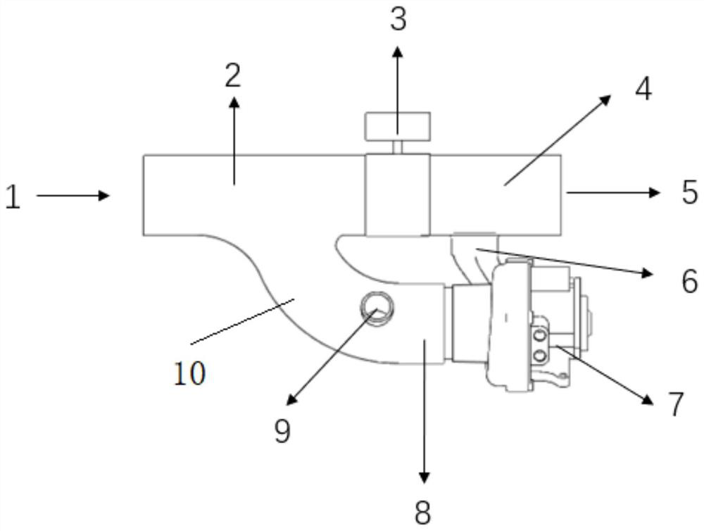
[0025] Such as figure 1 As shown, the present invention provides a controllable electric supercharging device for an engine, which is characterized in that it includes a connecting pipe on which an electric control valve 3 is arranged, and the electric control valve 3 divides the connecting pipe into the first connecting pipe 2 and the second connecting pipe 4; the port of the first connecting pipe 2 is used as the inlet 1 of the electric supercharger, and the port of the second connecting pipe 4 is used as the outlet 5 of the electric supercharging device; the side of the first connecting pipe 2 extends outward A third connecting pipe 10 is formed, and the third connecting pipe 10 communicates with the first connecting pipe 2; T...


PUM


Abstract

The invention provides a controllable electric supercharging device for an engine. The controllable electric supercharging device for an engine is characterized by comprising a connecting pipe, an electric control valve is arranged on the connecting pipe, and the connecting pipe is divided into a first connecting pipe and a second connecting pipe by a one-way valve; an end opening of the first connecting pipe serves as an inlet of the electric supercharging device, and an end opening of the second connecting pipe serves as an outlet of the electric supercharging device; the side surface of the first connecting pipe extends outwards to form a third connecting pipe, and the third connecting pipe communicates with the first connecting pipe; an electric supercharger is fixedly arranged at an end opening of the third connecting pipe, and the third connecting pipe communicates with an inlet of the electric supercharger; an outlet of the electric supercharger communicates with the second connecting pipe through a pipeline; and a compressed air inlet is formed in the side face of the end opening of the third connecting pipe, and compressed air enters the inlet of the electric supercharger through the third connecting pipe from the compressed air inlet. According to the controllable electric supercharging device for the engine, the required power of the electric supercharger is reduced, so that the heat productivity of a driving motor is reduced.

Description

technical field [0001] The invention relates to the technical field of engines, in particular to a controllable electric supercharging device for engines. Background technique [0002] Turbocharging is a technology that uses the exhaust gas generated by the engine to drive the air compressor. The purpose of supercharging is to increase the intake air volume of the engine without increasing the displacement of the engine, increase the equivalent compression ratio of the engine, and thereby increase the power density and torque density of the engine. [0003] When the engine is working, the high-temperature and high-pressure exhaust gas from the exhaust impacts the turbine blades at a high speed at a certain angle, driving the turbine to rotate at a high speed, and the turbine drives the coaxial compressor impeller to rotate at a high speed, so that the air is pressurized and enters the cylinder. When the engine speed increases, the exhaust gas discharge speed increases synch...

Claims


Application Information

Patent Timeline
Patent Type & Authority Applications(China)
IPC IPC(8): F02B37/04F02B37/12F02D41/00
CPCF02B37/04F02B37/12F02D41/0007F02D2200/04Y02T10/12
Inventor 李智陈珏范建权胡前谢毅吴博许振营
Owner DONGFENG COMML VEHICLE CO LTD
Why Eureka
Try Eureka