

Inner multi-cavity metal temperature control device
A temperature control device and metal technology, which is applied to the installation device of the container structure, the equipment loaded into the pressure vessel, and the equipment discharged from the pressure vessel, etc., can solve the problem of reducing the safety performance of the hydrogen charging device and reducing the hydrogen charging speed of hydrogen charging And other issues
- Summary
- Abstract
- Description
- Claims
- Application Information
AI Technical Summary
Problems solved by technology
Method used
Image

Examples
Embodiment 1
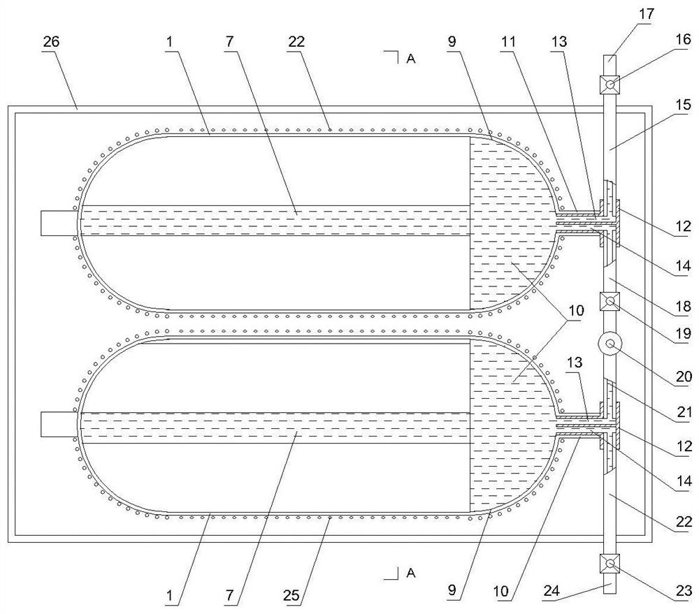
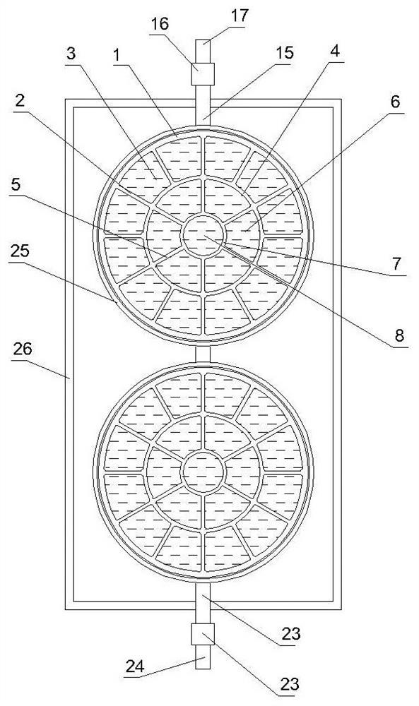
[0045] A cross-sectional structure of an inner multi-cavity low temperature metal hydrogen storage device such as figure 1 Distance figure 2 Yes figure 1 AA cross-sectional view, wherein: 1 is the outer wall of the metal hydrogen storage and hydrogen supply unit, 2 is the outer rumor, and 3 is the outer ring storage chamber, and 4 is the medium ring wall, 5 is a neutron, 6 is a neutral storage cavity, 7 Is the inner ring wall, 8 is the inner ring storage chamber, 9 is the hydrogen storage chamber, 10 is hydrogen, 11 is a hydrogen output input, 12 is a hydrogen valve, 13 is a valve input port, 14 is a valve output port, 15 is input The tube, 16 is the input cutoff valve, 17 is a hydrogen input opening, 18 is an output connecting tube, 19 is a connecting pipe shut-off valve, 20 is a hydrogen pump, 21 is an input connection tube, 22 is an output tube, 23 is an output shut-off valve, 24 is an output shut-off valve, 24 It is a hydrogen output port, 25 is carbon fibers, and 26 is a refr...
Embodiment 2
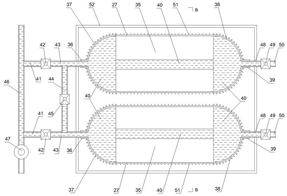
[0056] Structure of multi-cavity low temperature metal hydrogen storage hydrogen production apparatus in dual input and output port image 3 Distance Figure 4 Yes image 3 BB cross-sectional view, wherein: 27 is an aluminum alloy reservoir, 28 is an outer rumor, 29 is an outer ring reservoir, 30 is a neutral wall, 31 is a neutronium, 32 is a neutral storage chamber, 33 It is the inner ring wall, 34 is the inner cyclic storage chamber, 35 is a central multi-cavity, 36 is an input connection port, 37 is a hydrogen storage chamber, 38 is a foreign storage chamber, 39 is an output connection opening, 40 is hydrogen, 40 is hydrogen. 41 is a hydrogen inlet tube, 42 is a hydrogen inlet valve, 43 is a valve outlet tube, 44 is an inner connection, 45 is an inner connecting pipe shut-off valve, 46 is a hydrogen input conduit, 47 is a hydrogen pump, 48 is an output tube, 49 is The output tube shutoff valve, 50 is a hydrogen outlet, 51 is carbon fibers, 52 is a refrigeration device.
[0057] Wh...
Embodiment 3
[0064] An internal multi-cavity filled hydrogen storage material is schematic diagram of heat storage bottle section Figure 5 Distance Figure 6 Yes Figure 5 Schematic diagram of C-C aluminum alloy reservoir bottle section, Figure 7 Yes Figure 5 A schematic diagram of the cross-sectional structure of the CC aluminum alloy storage bottle cavity, wherein: 53 is an aluminum alloy reservoir, 54 is a multi-cavity, 55 is a hydrogen storage material chamber, 56 is a hydrogen storage material, 57 is The hydrogen passage, 58 is a electric heating tube hole, 59 is a electric heating tube, 60 is a hydrogen storage material separator, 62 is a screw, 63 is a hydrogen storage chamber, 64 is a hydrogen storage bottle, 65 is a hydrogen storage bottle The base, 66 is hydrogen, 67 is a hydrogen storage bottle valve, 68 is a hydrogen input tube, 69 is a input tube shut-off valve, 70 is an output tube shut-off valve, 71 is a hydrogen output tube, 72 is a carbon fiber, 73 is a refrigeration device.
[...
PUM
 Abstract
Description
Claims
Application Information