
Vertical sintering furnace convenient to clean

A sintering furnace, vertical technology, applied in the direction of vertical furnaces, furnaces, furnace materials, etc., can solve problems such as poor cleaning, affecting use, and affecting the quality of sintered products, and achieve the effect of improving production efficiency and speeding up cleaning time

Pending Publication Date: 2021-06-29
王建生
View PDF11 Cites 7 Cited by
  • Summary
  • Abstract
  • Description
  • Claims
  • Application Information

AI Technical Summary

Problems solved by technology

[0004] At present, the inner cavity of existing sintering furnaces often uses iron materials, which will produce a lot of rust during use, which will affect the quality of sintered products. At the same time, when using a sintering device to sinter silicon chips, the Impurities are often produced after sintering. These impurities are very difficult to clean in the sintering furnace, which increases the workload of the staff and affects the use of the next sintering;

Method used


Image

  • Vertical sintering furnace convenient to clean
  • Vertical sintering furnace convenient to clean
  • Vertical sintering furnace convenient to clean

Examples


Embodiment Construction

[0075] The following description serves to disclose the present invention to enable those skilled in the art to carry out the present invention. The preferred embodiments described below are only examples, and those skilled in the art can devise other obvious variations.

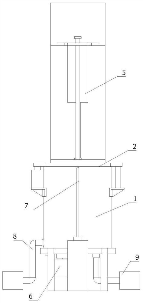
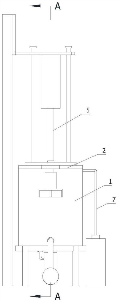
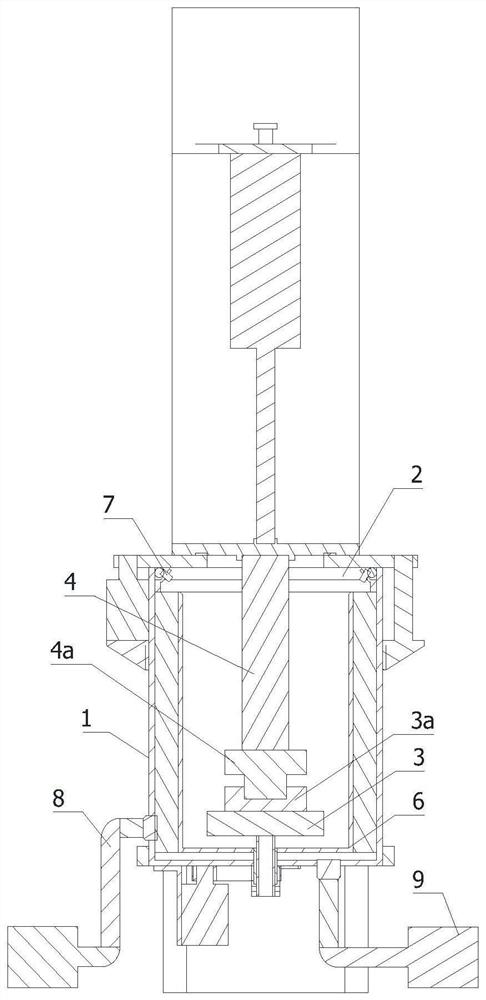
[0076] refer to Figure 1 to Figure 3 As shown, an easy-to-clean vertical sintering furnace, including:

[0077] Sintering furnace 1;

[0078] The sealing ring group 2 is arranged on the top of the sintering furnace 1;

[0079] The lower electrode 3 is arranged inside the sintering furnace 1, and the top of the lower electrode 3 is provided with a mold;

[0080] The upper electrode 4, the bottom of the upper electrode 4 is provided with an indenter 4a;

[0081] The pressing mechanism 5 is arranged on the side of the sintering furnace 1, and the upper electrode 4 is arranged at the output end of the pressing mechanism 5;

[0082] The cleaning mechanism 6 is arranged at the bottom of the sintering furnace...


PUM


Abstract

The invention relates to the technical field of sintering furnace equipment, in particular to a vertical sintering furnace convenient to clean. The vertical sintering furnace convenient to clean comprises a sintering furnace, a sealing ring set, a lower electrode, an upper electrode, a downward pressing mechanism, a cleaning mechanism, a water cooling mechanism, an air pressure control mechanism and a drainage mechanism. The sealing ring set is arranged at the top of the sintering furnace. The lower electrode is arranged in the sintering furnace, and a mold is arranged at the top of the lower electrode. A pressure head is arranged at the bottom of the upper electrode. The downward pressing mechanism is arranged on the side of the sintering furnace, and the upper electrode is arranged at the output end of the downward pressing mechanism. The cleaning mechanism is arranged at the bottom of the sintering furnace, the water cooling mechanism is arranged outside the sintering furnace, and the output end of the water cooling mechanism is located in the sintering furnace. The air pressure control mechanism is arranged outside the sintering furnace, and the output end of the air pressure control mechanism communicates with the interior of the sintering furnace. The drainage mechanism is arranged at the bottom of the sintering furnace, and the output end of the drainage mechanism communicates with the interior of the sintering furnace. According to the technical scheme, products can be sintered, the interior of the furnace can be rapidly cleaned in time, the cleaning time is shortened, and the production efficiency is improved.

Description

technical field [0001] The invention relates to the technical field of sintering furnace equipment, in particular to a vertical sintering furnace that is easy to clean. Background technique [0002] The sintering furnace refers to the special equipment for obtaining the required physical and mechanical properties and microstructure of the powder compact through sintering. The sintering furnace is used to dry the slurry on the silicon wafer, remove the organic components in the slurry, and complete the aluminum back field and grid wire sintering; [0003] In order to ensure the dewaxing (lubricant or forming agent), reduction, alloying, and structural transformation of the powder compact during the sintering process, it is necessary to adjust the sintering temperature, protective atmosphere, compact transfer mode, heating and cooling speed during sintering. and so on for precise control; [0004] At present, the inner cavity of existing sintering furnaces often uses iron ma...

Claims


Application Information

Patent Timeline
Patent Type & Authority Applications(China)
IPC IPC(8): F27B1/09F27B1/24F27D25/00
CPCF27B1/08F27B1/005F27B1/24F27D25/001F27M2003/04
Inventor 王建生梁惠文
Owner 王建生
Learn More