Supercharge Your Innovation With Domain-Expert AI Agents!

Auxiliary assembling device in current-conducting rod assembling

A technology of conductive rods and auxiliary groups, applied in the direction of manufacturing tools, hand-held tools, etc., can solve the problems of slow assembly process, increased labor intensity, and pressure on one side of the conductive rod assembly process, so as to achieve accurate product coordination and improve assembly efficiency. Effect

Active Publication Date: 2021-07-02
ZHEJIANG DISIWEI ELECTRIC
View PDF6 Cites 0 Cited by
  • Summary
  • Abstract
  • Description
  • Claims
  • Application Information

AI Technical Summary

Problems solved by technology

[0002] At present, when the existing conductive rods of TGF8, TGF26, and f15 are assembled, the center is calibrated after installing and positioning the tooling through the bench drill, and the assembly is completed by pressing down manually. However, this assembly method has the following disadvantages: 1. Manual calibration, the conductive rod will be pressed on one side during the assembly process, resulting in the interference fit of the conductive rod during assembly, and the copper powder will be pressed out. It needs to be blown with an air gun before continuing to assemble; 2. Install the tooling before each assembly And manual pressing requires a lot of strength to work for a long time; 3. After each assembly work, employees have been pressing down manually, causing blistering in the palm of their hands, and because they often press one side, they need to press while watching , Make sure that there is no copper scrap between the conductive rods and then press to the bottom, if there is any, blow air treatment; 4. The connection of the conductive rods needs to be adjusted with eyes and hands, which makes the assembly process slow and labor intensity increases.

Method used


Image

  • Auxiliary assembling device in current-conducting rod assembling
  • Auxiliary assembling device in current-conducting rod assembling
  • Auxiliary assembling device in current-conducting rod assembling

Examples


Embodiment Construction

[0040] The following will clearly and completely describe the technical solutions in the embodiments of the present invention with reference to the accompanying drawings in the embodiments of the present invention. Obviously, the described embodiments are only some, not all, embodiments of the present invention. Based on the embodiments of the present invention, all other embodiments obtained by persons of ordinary skill in the art without making creative efforts belong to the protection scope of the present invention.

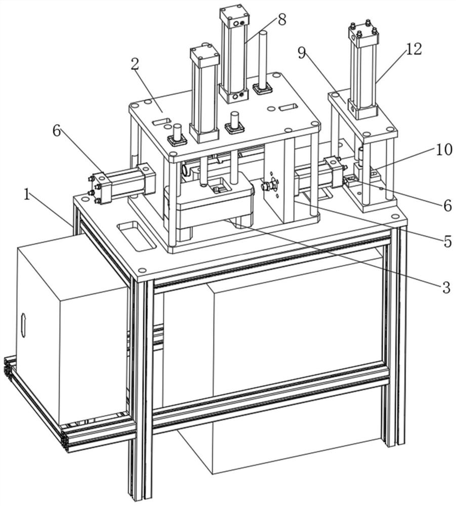
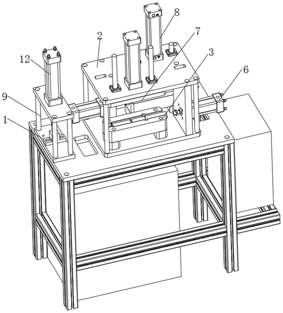
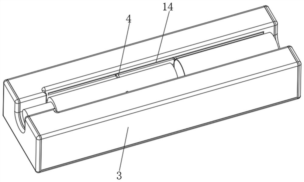
[0041] see Figure 1-13 , the present invention provides a technical solution: an auxiliary assembly device in the assembly of conductive rods, including a workbench 1 for assembly, a support frame 2 is provided on the workbench 1, and two groups of pairs of TGF8 are provided on the support frame 2 The first mold 3 for assembling the / TGF26 type conductive rod, the inside of the first mold 3 is provided with a connecting device 4 for connecting the TGF8 / TGF26 ...


PUM


Abstract

The invention discloses an auxiliary assembling device in current-conducting rod assembling. The auxiliary assembling device comprises a workbench for assembling, wherein a support frame is arranged on the workbench, two groups of first molds for assembling a TGF8 / TGF26 type current-conducting rod are arranged on the support frame, and connecting devices for connecting the TGF8 / TGF26 type current-conducting rod during assembling are arranged in the first molds. According to the auxiliary assembly device in current-conducting rod assembling, the current-conducting rod is placed in a corresponding tool mold, a pneumatic switch is shifted to limit the current-conducting rod, then an oil cylinder is pressed down to drive button equipment for assembly, the equipment adopts a pneumatic and oil-driven mode, the high-strength assembly process is omitted manually. The device integrates assembling tools for three types of current-conducting rods, installation of tool clamps and occupation of equipment are omitted, the working process of center calibration is omitted manually, the size precision of a connecting device and a positioning device is controlled in place, the extrusion condition of copper powder in the current-conducting rod assembling process is avoided, and product matching is more accurate.

Description

technical field [0001] The invention relates to the technical field of conducting rod assembly, in particular to an auxiliary assembly device in conducting rod assembly. Background technique [0002] At present, when the existing conductive rods of TGF8, TGF26, and f15 are assembled, the center is calibrated after installing and positioning the tooling through the bench drill, and the assembly is completed by pressing down manually. However, this assembly method has the following disadvantages: 1. Manual calibration, the conductive rod will be pressed on one side during the assembly process, resulting in the interference fit of the conductive rod during assembly, and the copper powder will be pressed out. It needs to be blown with an air gun before continuing to assemble; 2. Install the tooling before each assembly And manual pressing requires a lot of strength to work for a long time; 3. After each assembly work, employees have been pressing down manually, causing blisterin...

Claims


Application Information

Patent Timeline
IPC IPC(8): B25B27/00
CPCB25B27/00
Inventor 余永松应兵荣张庆军方强杨建飞张能响谢苏龙
Owner ZHEJIANG DISIWEI ELECTRIC
Features
  • R&D
  • Intellectual Property
  • Life Sciences
  • Materials
  • Tech Scout
  • Unparalleled Data Quality
  • Higher Quality Content
  • 60% Fewer Hallucinations
Learn More