A space-borne helical antenna feeding structure and helical antenna

A helical antenna and space-borne technology, which is applied in the field of helical antenna feed structure, can solve problems such as not being able to meet high reliability requirements, and achieve the effects of improving reliability, avoiding breakage, and smooth and stable signal transmission

Active Publication Date: 2022-04-19
SOUTHWEST CHINA RES INST OF ELECTRONICS EQUIP
View PDF10 Cites 0 Cited by
  • Summary
  • Abstract
  • Description
  • Claims
  • Application Information

AI Technical Summary

Problems solved by technology

[0008] In order to overcome the deficiencies of the prior art, the present invention provides a space-borne helical antenna feed structure and helical antenna, which solves the problems existing in the prior art that cannot meet the requirements of the microstrip line of the helical antenna in harsh environments such as strong vibration and severe temperature changes. The high reliability requirements of the interconnection feed structure with the radiator, etc.

Method used


Image

  • A space-borne helical antenna feeding structure and helical antenna
  • A space-borne helical antenna feeding structure and helical antenna
  • A space-borne helical antenna feeding structure and helical antenna

Examples


Embodiment 1

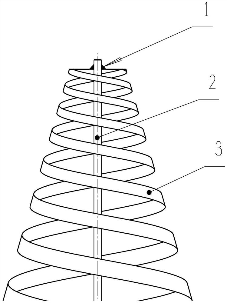
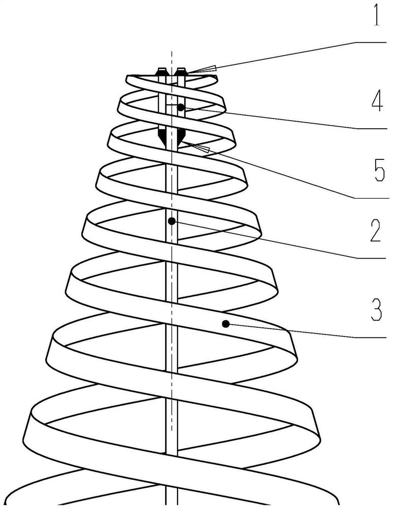
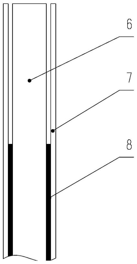
[0053] like Figure 1 to Figure 8 As shown, a feed structure for a space-borne helical antenna includes a microstrip line 2 and a radiator 3 sleeved outside the microstrip line 2. The microstrip line 2 includes a rigid dielectric substrate 6 and is arranged on a rigid dielectric substrate 6, the flexible dielectric substrate 7 on both sides, and the adhesive layer 8 connected between the rigid dielectric substrate 6 and the flexible dielectric substrate 7, the flexible dielectric substrate 7 can be bent in a direction away from the rigid dielectric substrate 6, and the flexible A feeding circuit layer 11 is provided on the side of the dielectric substrate 7 away from the rigid dielectric substrate 6 , and the top of the adhesive layer 8 is located above the bottom of the feeding circuit layer 11 .

[0054] The rigid dielectric substrate 6, the flexible dielectric substrate 7, the adhesive layer 8, and the feed circuit layer 11 together constitute a new microstrip line 2 struct...

Embodiment 2

[0063] like Figure 1 to Figure 8 As shown, as a further optimization of Embodiment 1, this embodiment includes all the technical features of Embodiment 1. In addition, this embodiment also includes the following technical features:

[0064] As a preferred technical solution, lugs 12 are provided on the outside of the flexible dielectric substrate 7, a support device 13 is provided between the microstrip line 2 and the radiator 3, and a support device 13 is provided on the support device 13. A groove 14 cooperating with the lug 12 .

[0065] Lugs 12 are arranged on the structure of the microstrip line 2, preferably a group of lugs 12 are respectively arranged on the outer sides of the upper and lower parts of the flexible dielectric substrate 7 of the microstrip line 2 (one convex is respectively arranged on the left and right sides of the upper part of the flexible dielectric substrate 7). ear 12, a lug 12 is provided on the left and right sides of the bottom of the flexible...

Embodiment 3

[0075] A helical antenna includes the above-mentioned feeding structure of the space-borne helical antenna.

[0076] The rigid dielectric substrate 6, the flexible dielectric substrate 7, the adhesive layer 8, and the feed circuit layer 11 together constitute a new microstrip line 2 structure, which has the characteristics of rigid-flex combination. Among them, the rigid dielectric substrate 6 is used as the support of the microstrip line 2, and the left and right outer sides of the flexible dielectric substrate 7 are provided with a feed circuit layer 11 (preferably a printed board feed circuit, the size of the printed board circuit is small, the assembly process is simple, High installation efficiency, high circuit reliability), the flexible dielectric substrate 7 and the rigid dielectric substrate 6 are bonded and fixed, but no bonding is performed at the bend of the feed circuit layer 11 of the flexible dielectric substrate 7 and above, so that The flexible dielectric subs...


PUM


Abstract

The invention discloses a space-borne helical antenna feeding structure and a helical antenna. The feeding structure includes a microstrip line and a radiator sleeved outside the microstrip line. The microstrip line includes a rigid dielectric substrate and a The flexible dielectric substrate on both sides of the rigid dielectric substrate, the adhesive layer connected between the rigid dielectric substrate and the flexible dielectric substrate, the flexible dielectric substrate can be bent in a direction away from the rigid dielectric substrate, and the flexible dielectric substrate is far away from the rigid dielectric substrate. A feed circuit layer is provided on one side of the dielectric substrate, and the top of the adhesive layer is located above the bottom of the feed circuit layer. The invention solves the problems existing in the prior art that it cannot meet the high reliability requirements of the interconnection feed structure between the microstrip line of the helical antenna and the radiator in harsh environments such as strong vibration and severe temperature change.

Description

technical field [0001] The invention relates to the technical field of a helical antenna feeding structure, in particular to a space-borne helical antenna feeding structure and the helical antenna. Background technique [0002] Helical antennas have significant advantages such as ultra-wideband, good front-to-back ratio of pattern, constant gain, good wide-angle-to-axis ratio, small size, and light weight. Currently, they are more and more widely used in aerospace, radar, and communication technology fields. Spaceborne antennas are usually not maintainable. The installation and use environment of these spaceborne antennas is often very harsh, the temperature changes extremely sharply, and the operating temperature range is extremely wide (-140°C ~ +100°C); in addition, these antennas also need to withstand The vibration and shock during the satellite launch phase requires these spaceborne antennas to have high reliability to adapt to the harsh temperature and mechanical envi...

Claims


Application Information

Patent Timeline
Patent Type & Authority Patents(China)
IPC IPC(8): H01Q1/36H01Q1/50
CPCH01Q1/36H01Q1/50
Inventor 刘颖何亚东张登材林玉敏叶君永郭峥李鹏林鑫超
Owner SOUTHWEST CHINA RES INST OF ELECTRONICS EQUIP
Why Eureka
Try Eureka