Structure of combined cathode steel bar and cathode carbon block set

A technology of cathode carbon block and cathode steel rod, which is applied in the field of electrolytic cells, can solve the problems of complex structure of the cathode end, lack of large-scale industrial application, and large horizontal heat dissipation of the cathode end.

Pending Publication Date: 2021-07-06
李欣
View PDF12 Cites 0 Cited by
  • Summary
  • Abstract
  • Description
  • Claims
  • Application Information

AI Technical Summary

Problems solved by technology

[0003] Patent CN101451249B proposes a cathode structure in which a conductor is arranged at or below the cathode carbon block, and the current flows directly from the bottom of the tank, which can eliminate the horizontal current in the aluminum liquid from the source, but due to safety considerations, this method does not make much sense. Large-scale industrial application; patents CN102268695A and US6231745B1 propose to use high-conductivity copper or other high-conductivity materials to replace the cathode current collection method of steel rods or some steel rods, which can transfer the horizontal current from the aluminum liquid layer to the bottom of the

Method used


Image

  • Structure of combined cathode steel bar and cathode carbon block set
  • Structure of combined cathode steel bar and cathode carbon block set
  • Structure of combined cathode steel bar and cathode carbon block set

Examples


Embodiment 1

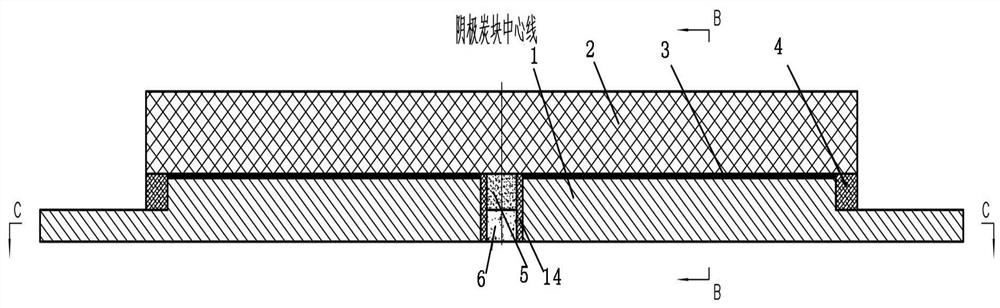
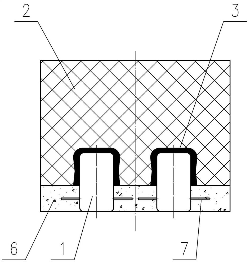
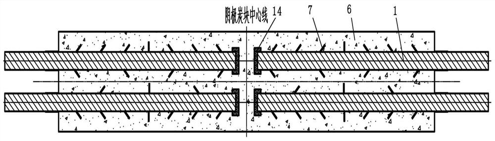
[0043] Such as Figure 1-3 As shown, a composite cathode steel rod and cathode carbon block group structure, the cathode steel rod 1 is fixed at the lower part of the cathode carbon block 2 through a solid carbon paste or phosphorus pig iron 3, and the cathode steel rod 1 is exposed at the lower part of the cathode carbon block 2 Casting with refractory and anti-seepage castable 6, the cross section of cathode steel rod 1 near the end of cathode carbon block 2 in the cathode block steel rod groove becomes smaller, and the end part is filled with high temperature resistant and compressible in the space formed in this area Material 4, to absorb the thermal expansion of the cathode steel rod. A central high temperature resistant compressible material 14 is provided outside the end of the cathode steel rod 1 below the middle of the cathode carbon block 2 to absorb the thermal expansion of the cathode steel rod. There are four cathode steel rods 1, which are arranged symmetrically...

Embodiment 2

[0049] Such as Figure 4As shown, a composite cathode steel rod and cathode carbon block group structure, the cathode steel rod 1 is fastened and fixed by carbon paste at the lower part of the cathode carbon block 2, and the exposed part of the cathode steel rod 1 is fire-resistant and seepage-proof at the lower part of the cathode carbon block 2 The pouring material 6 is poured, and the section of the cathode steel rod 1 close to the end of the cathode block 2 in the cathode block becomes smaller, and the space formed in this area is filled with a high-temperature-resistant compressible material 4 at the end to absorb the cathode Thermal expansion of the steel rod. A central high temperature resistant compressible material 14 is provided outside the end of the cathode steel rod 1 below the middle of the cathode carbon block 2 to absorb the thermal expansion of the cathode steel rod. There are four cathode steel rods 1, which are arranged symmetrically with the center line of...

Embodiment 3

[0054] Such as Figure 5 As shown, both sides of the protruding end of the cathode steel rod 1 in embodiment 1 increase its cross-sectional area by welding to reduce the resistance of this part of the cathode steel rod 1, and the others are the same as in embodiment 1.


PUM


Abstract

The invention relates to an electrolytic tank in the aluminum electrolysis technology, in particular to a structure of a combined cathode steel bar and cathode carbon block set in the electrolytic tank. Cathode steel bars are fixed to the lower portion of a cathode carbon block through carbon paste binding or cast iron casting, the areas, exposed out of the lower portion of the cathode carbon block, of the cathode steel bars are cast through fireproof anti-seepage casting materials, the sections of the portions, close to the end of the cathode carbon block, of the cathode steel bars in cathode carbon block steel bar grooves become small, the spaces formed in the areas are filled with high-temperature-resistant compressible materials, and high-temperature-resistant compressible materials are arranged on the outer sides of the end parts of the cathode steel bars at the bottom of the middle part of the cathode carbon block. The structure has the advantages and effects that the horizontal current and the cathode voltage drop in molten aluminum are substantially reduced, a regular space can be formed at the end of the cathode carbon block, horizontal heat dissipation at the end of the cathode carbon block is effectively reduced, good furnace wall and stretching leg shapes can be formed advantageously, the magnetic fluid stability and the heat balance stability of the electrolytic tank are improved, the lining design and the heat balance design are conducted advantageously, and the probability of tank leakage at the position is substantially reduced.

Description

technical field [0001] The invention relates to an electrolytic cell in the aluminum electrolysis technology, in particular to a structure of a composite cathode steel rod and a cathode carbon block group in the electrolytic cell. Background technique [0002] The development trend of today's aluminum electrolysis technology is to focus on the large-scale and high stability of the electrolytic cell, and strive to pursue high current efficiency and low power consumption of the electrolytic cell. This development trend puts forward higher requirements for the design of the horizontal current in the aluminum liquid in the electrolytic cell and the pressure drop of the cathode group, and at the same time, the regional heat balance of the electrolytic cell should also be taken into account. The design of the cathode structure (or steel rod) is one of the current research hotspots. [0003] Patent CN101451249B proposes a cathode structure in which a conductor is arranged at or be...

Claims


Application Information

Patent Timeline
IPC IPC(8): C25C3/08
CPCC25C3/08
Inventor 李欣
Owner 李欣
Why Eureka
Try Eureka