Anti-collapse device for expressway tunnel engineering

A technology for tunnel engineering and highways, applied in tunnels, tunnel linings, shaft equipment, etc., can solve problems such as bulky volume, affecting the speed of tunnel construction, and low structural strength of cast-in-place concrete.

Active Publication Date: 2021-07-06
刘京津
View PDF8 Cites 3 Cited by
  • Summary
  • Abstract
  • Description
  • Claims
  • Application Information

AI Technical Summary

Problems solved by technology

[0003] At present, although the existing tunnel trolley can play a role in preventing landslides in the tunnel, its structure is relatively fixed and bulky, and it can only be moved forward to support the newly excavated tunnel wall after the poured concrete has hardened. Obviously, this method of intermittent excavation affects the speed of tunnel construction, and the surface of the steel formwork of the tunnel trolley is smooth, and the concrete has no arch ribs after pouring, resulting in a weak cast-in-place concrete structure in the tunnel

Method used


Image

  • Anti-collapse device for expressway tunnel engineering
  • Anti-collapse device for expressway tunnel engineering
  • Anti-collapse device for expressway tunnel engineering

Examples


Embodiment 1

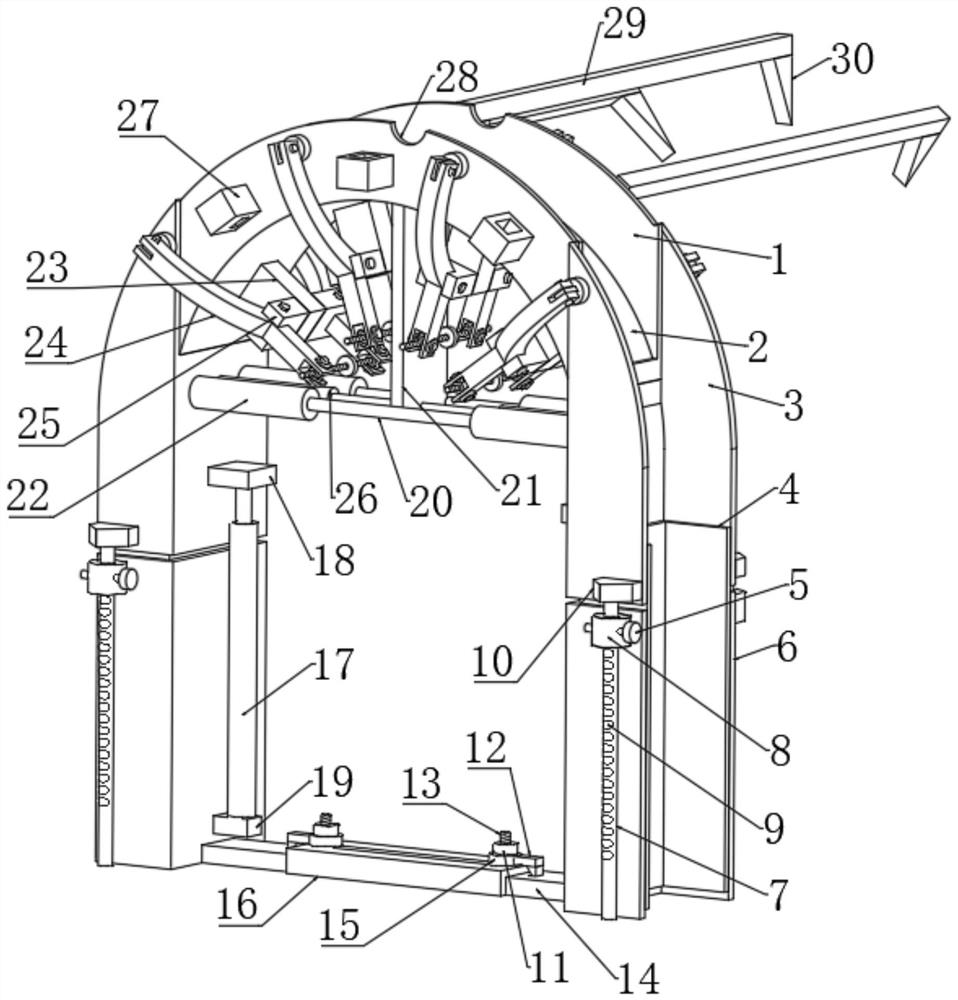
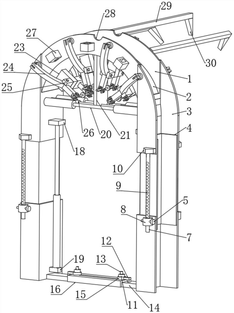
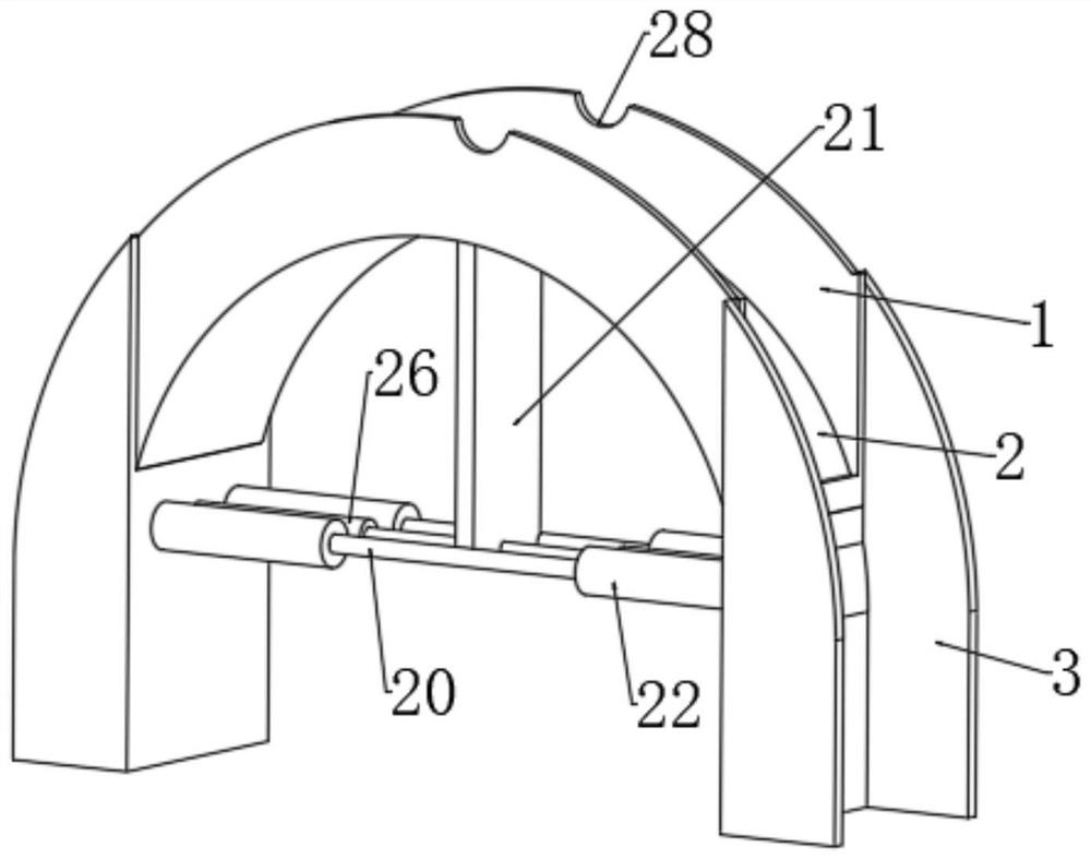
[0028] refer to Figure 1 to Figure 7, an anti-collapse device for expressway tunnel engineering, comprising a web 2 and a support rod 29, the upper end of the web 2 is symmetrically fixedly connected with two wing plates 1, and the upper edges of the two wing plates 1 are provided with grouting gaps 28. The center of the lower end of the web 2 is fixedly connected with a support plate 21, and the lower end of the support plate 21 is fixedly connected with two cross bars 20. The lower end of the web 2 is provided with two first steel molds 3, two first steel molds The opposite side of the mold 3 is fixedly connected with two horizontal tubes 22, and the two horizontal tubes 22 are respectively slidingly socketed with the rod walls of the two horizontal bars 20, and the opposite sides of the support plate 21 are fixedly connected with the first hydraulic cylinder 26 , the opposite ends of the two first hydraulic cylinders 26 are respectively fixedly connected to the side walls ...

Embodiment 2

[0030] Embodiment 2: the difference based on Embodiment 1 is;

[0031] refer to figure 2 and Figure 6 , the connection mechanism includes a fixed block 18, one end of the fixed block 18 is fixedly connected with the side wall of the first steel mold 3, the lower end of the fixed block 18 is fixedly connected with the second hydraulic cylinder 17, and the lower end of the second hydraulic cylinder 17 is fixedly connected with a support block 19, one end of the support block 19 is fixedly connected to one side of the third steel mold 6, the opposite sides of the first steel mold 3 are fixedly connected with installation blocks 10, and the lower ends of the two installation blocks 10 are fixedly connected with positioning rods 7. A positioning sleeve 8 is slidingly sleeved on the rod wall of the positioning rod 7, and one side of the positioning sleeve 8 is fixedly connected with one side of the third steel mold 6. One side of the positioning sleeve 8 is provided with a positi...

Embodiment 3

[0034] Embodiment 3: the difference based on embodiment 1 is;

[0035] refer to Figure 5 , the positioning mechanism includes two positioning curved rods 24, and one end of the two positioning curved rods 24 is provided with a mounting groove, and in the two mounting grooves, an internal threaded pipe 31 is connected through a rotating shaft, and one side of the connecting block 23 is provided with a two-way Screw rod 32, the rod wall row of two-way screw rod 32 is threadedly connected with internally threaded pipe 31 in two mounting grooves respectively, and the center of the rod wall of two-way screw rod 32 is fixedly connected with hand wheel 33, and the rod wall of positioning bending rod 24 A U-shaped block 25 is rotatably connected by a pin, and one side of the U-shaped block 25 is fixedly connected with one side of the connecting block 23. The end of the positioning curved rod 24 away from the installation groove is provided with an assembly groove, and the pin shaft i...


PUM


Abstract

The invention relates to the technical field of tunnel engineering equipment, and discloses an anti-collapse device for expressway tunnel engineering. The anti-collapse device comprises a web plate and a supporting rod, wherein two wing plates are symmetrically and fixedly connected to the upper end of the web plate; grouting notches are formed in the edges of the upper ends of the two wing plates; a supporting plate is fixedly connected to the center of the lower end of the web plate; two transverse rods are fixedly connected to the lower end of the supporting plate; two first steel molds are arranged at the lower end of the web plate; two transverse pipes are fixedly connected to the opposite sides of the two first steel molds; the two transverse pipes are in sliding sleeve connection with the rod walls of the two transverse rods correspondingly; and first hydraulic cylinders are fixedly connected to the two opposite sides of the supporting plate. The anti-collapse device for expressway tunnel engineering can conveniently move in a tunnel, along with the excavation speed of the tunnel, a support is continuously disassembled and assembled, the tunnel construction speed is increased, concrete formed through pouring has an arch rib structure, and the strength of the anti-collapse structure of the tunnel is greatly improved.

Description

technical field [0001] The invention relates to the technical field of tunnel engineering equipment, in particular to an anti-collapse device for expressway tunnel engineering. Background technique [0002] Expressway tunnels are passageways specially used for automobile transportation. With the development of social economy and production, expressways have appeared in large numbers, and higher standards have been put forward for road construction technology, requiring straight lines, gentle slopes, and spacious road surfaces. Therefore, when the road passes through the mountainous area, the scheme of detour around the mountain in the past is mostly changed to the tunnel scheme. The construction of tunnels plays an important role in improving the technical status of highways, shortening running distances, increasing transportation capacity, and reducing accidents. During tunnel construction, it is necessary to strengthen the excavated tunnel wall. During reinforcement, a tu...

Claims


Application Information

Patent Timeline
Patent Type & Authority Applications(China)
IPC IPC(8): E21D15/14E21D15/50E21D15/56E21D11/10E21D11/18
CPCE21D15/14E21D15/50E21D15/56E21D11/102E21D11/18Y02A30/60
Inventor 刘京津张连黄嘉明
Owner 刘京津
Why Eureka
Try Eureka