Pressure-limiting overflow device for hydraulic axial plunger pump

An axial piston pump and overflow device technology, applied in pump control, pump testing, liquid variable capacity machinery, etc., can solve the problems of no pressure monitoring and increase the difficulty of processing mainstream pipes.

Inactive Publication Date: 2021-07-06
XIAN AERONAUTICAL UNIV
View PDF10 Cites 0 Cited by
  • Summary
  • Abstract
  • Description
  • Claims
  • Application Information

AI Technical Summary

Problems solved by technology

[0003] The existing pressure-limiting overflow device for hydraulic axial piston pumps does not monitor the pressure in real time, and measures the pressure in the mai

Method used


Image

  • Pressure-limiting overflow device for hydraulic axial plunger pump
  • Pressure-limiting overflow device for hydraulic axial plunger pump
  • Pressure-limiting overflow device for hydraulic axial plunger pump

Examples


Embodiment 1

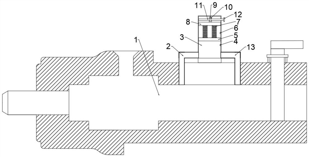
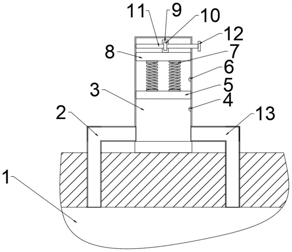
[0031] refer to Figure 1 ~ Figure 2 , a pressure limiting overflow device for a hydraulic axial piston pump, comprising a flow pipe 1, the side of the flow pipe 1 is bolted to an inflow pipe 2 and the end of the inflow pipe 2 away from the flow pipe 1 is bolted to a pressure measuring pipe 3 , the inside of the pressure measuring tube 3 is provided with a pressure measuring mechanism, the pressure measuring mechanism includes a lower sensor 4, a sliding plate 5, an upper sensor 6, a first spring 7 and a sealing adjustment plate 8, and the inside of the pressure measuring tube 3 is slidably connected with a sliding plate 5 and the side of the sliding plate 5 far away from the inflow pipe 2 is bolted with several first springs 7, and the end of the first spring 7 far away from the sliding plate 5 is bolted with a sealing adjustment plate that is sealed and slidably connected with the inner shell wall of the pressure measuring tube 3 8. An adjustment mechanism for adjusting the ...

Embodiment 2

[0038] refer to Figure 5 , a pressure limiting overflow device for a hydraulic axial piston pump. Compared with Embodiment 1, the limiting mechanism of this embodiment includes a fixed block 18, a limiting plate 22 and a second spring 23, and the inside of the limiting box 14 A fixed block 18 is connected with a bolt near the position of the driving gear 17, and a plurality of limiting plates 22 abutting against the driving gear 17 are rotatably connected on the fixed block 18, and a second spring is arranged between the limiting plate 22 and the fixing block 18. 23. The limit plate 22 is provided with an electromagnetic mechanism on the side close to the fixed block 18. When the device is running, the limit plate 22 is used to limit the position of the driving gear 17, so as to avoid the blocking plate driving the connecting shaft 15 under the action of pressure. Rotate, and after adjustment, can avoid blocking plate to produce sliding, increase the applicability of device, ...


PUM


Abstract

The invention discloses a pressure-limiting overflow device for a hydraulic axial plunger pump, and relates to the field of hydraulic transmission. The pressure-limiting overflow device comprises a runner pipe, an inflow pipe is arranged on the side of the runner pipe, a pressure measuring pipe is arranged at one end, away from the runner pipe, of the inflow pipe, a pressure measuring mechanism is arranged in the pressure measuring pipe, a flow limiting box is arranged in the conveying direction of the runner pipe, and a flow limiting mechanism is arranged in the flow limiting box. When the device runs, hydraulic oil in a circulation pipe enters the pressure measuring pipe through an inflow pipe, the elastic force of a first spring is not enough to enable a sealing adjusting plate to relatively slide, when the pressure in the runner pipe is changed, a sliding plate slides in the pressure measuring pipe, when the sliding plate touches a lower sensor or an upper sensor, an alarm is given out, consequently, operator is reminded of regulation and control, if the detected pressure range needs to be adjusted, the vertical position of the sealing adjusting plate can be adjusted by using an adjusting mechanism, so that the monitored pressure range can be changed, and the device is suitable for large-scale popularization.

Description

technical field [0001] The invention relates to the technical field of hydraulic transmission, in particular to a pressure limiting overflow device for a hydraulic axial piston pump. Background technique [0002] The axial piston pump is a swash plate axial piston pump that uses an oil distribution plate to distribute oil, the cylinder rotates, and the variable head is variable. Axial piston pumps have a variety of variables to meet the requirements of users. It is widely used in machine tool forging, metallurgy, engineering, mining, ships and other machinery and other hydraulic transmission systems. [0003] The existing pressure-limiting overflow device for hydraulic axial piston pumps does not monitor the pressure in real time, and measures the pressure in the main flow pipe, which increases the processing difficulty of the main flow pipe. Pressure limiting relief device for hydraulic axial piston pumps with pressure monitoring. Contents of the invention [0004] The ...

Claims


Application Information

Patent Timeline
IPC IPC(8): F04B49/10F04B49/22F04B51/00
CPCF04B49/10F04B49/225F04B51/00
Inventor 张庆阳李祥阳卿绿军陶佳欣雷竹峰
Owner XIAN AERONAUTICAL UNIV
Why Eureka
Try Eureka