Landing buffer system drop test device and method

A technology of a buffer system and a test device, which is used in measurement devices, impact testing, aircraft component testing, etc., can solve problems such as the complex structure of the unlocking mechanism and each component, the large size and structural foundation of the whole machine, and the offset of the impact position. The effect of shortening the falling stroke and the height of the whole machine, improving the safety of the experiment and reducing the height of the whole machine

Active Publication Date: 2022-03-01
SHANGHAI JIAOTONG UNIV
View PDF6 Cites 0 Cited by
  • Summary
  • Abstract
  • Description
  • Claims
  • Application Information

AI Technical Summary

Problems solved by technology

At present, the traditional drop vibration test device is verified by the free fall of the buffer system. In order to achieve the upper limit of the impact speed, this kind of drop vibration test device usually has a very high vertical height, the overall size and structural foundation are large, and the center of gravity is relatively high. Turning moment Larger, the impact position is shifted, and there are potential safety hazards
For large-load landers, the traditional drop-shock test device needs to be designed for a higher drop height, which has greater adverse effects
[0005] Patent document CN111735598A discloses a new type of multi-condition drop shock test device and test method for a landing buffer mechanism. The device includes a bench system, a lifting system, a drop shock system and a load collection system. The vibration system is set on the platform system and can slide vertically, and the load acquisition system is set under the drop vibration system; adjust the landing attitude of the landing legs in the drop vibration system, and fix the landing attitude, and raise the drop vibration system to the predetermined level. The height is unlocked by the unlocking mechanism, and the drop shock system slides freely along the cylindrical guide rail under the action of gravity, so that the foot pads on the landing legs are in contact with the three-dimensional force measuring platform to simulate the collision process between the lander and the ground and record the data. The unlocking mechanism and components in the design are complex and need to be further optimized

Method used


Image

  • Landing buffer system drop test device and method
  • Landing buffer system drop test device and method
  • Landing buffer system drop test device and method

Examples


Embodiment Construction

[0098] The present invention will be described in detail below in conjunction with specific embodiments. The following examples will help those skilled in the art to further understand the present invention, but do not limit the present invention in any form. It should be noted that those skilled in the art can make several changes and improvements without departing from the concept of the present invention. These all belong to the protection scope of the present invention.

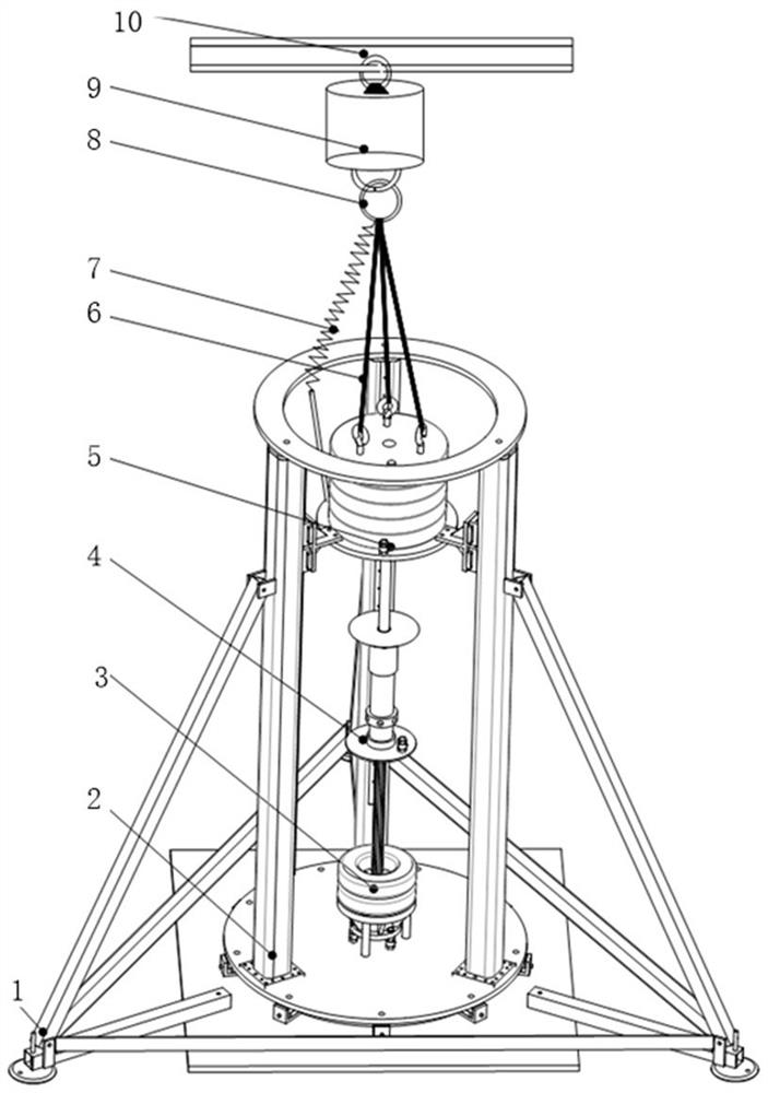
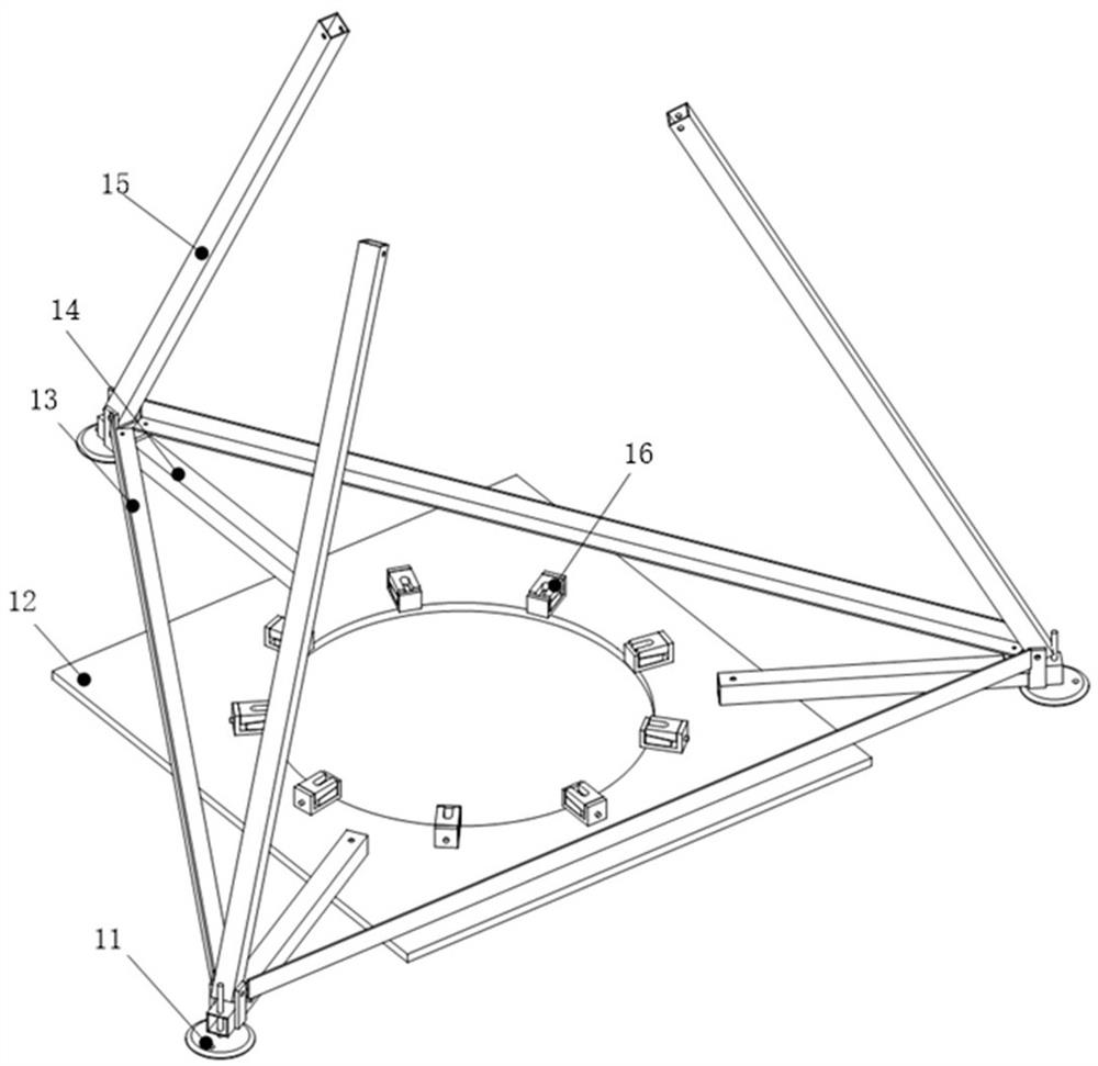
[0099] The invention provides a drop shock test device for a landing buffer system, such as figure 1 As shown, it includes a support system 1, a guide system 2, a buffer system 4, a counterweight system 5, a release system 9 and an acquisition system. During the test, the support system 1 is placed on a level ground, and the guide system 2 is preferably installed vertically on On the support system 1, the bottom end of the buffer system 4 is installed on the guide system 2, the fixed shaft 41 in the buf...


PUM


Abstract

The invention provides a landing shock test device and method for a landing buffer system, including a support system, a guide system, a buffer system, a counterweight system, a release system and an acquisition system, the guide system is installed on the support system, the The bottom end of the buffer system is installed on the guide system. The counterweight system includes a static state and a simulated landing state. When the counterweight system enters the simulated landing state from the static state under the control of the release system, it can Under the guidance of the guide system, it moves from the top of the buffer system towards the bottom of the buffer system and can stop under the action of the buffer system, and the acquisition system can collect physical quantity information generated due to the movement. The invention has the advantages of simple structure, low cost, convenient operation and installation, effectively reduces the height of the whole machine, and improves the safety of the experiment.

Description

technical field [0001] The present invention relates to the field of planetary surface landing buffer technology in the field of aerospace technology, in particular to a landing shock test device and method for a landing buffer system. Background technique [0002] The landing shock test is a dynamic characteristic test that simulates the aircraft landing and hitting the ground on a special test facility on the ground. It is used to verify whether the aircraft's structural strength, stiffness, buffer stroke, overload acceleration and other related indicators meet the design requirements. It is a landing buffer. A key part of design verification. [0003] With the successful landing of the Chang'e-5 lander, my country's three-step lunar exploration project has achieved complete success. In the future, our country will continue to implement multiple deep space exploration missions such as the exploration of the moon, Mars, asteroids, and Jupiter. Among them, the large-load l...

Claims


Application Information

Patent Timeline
Patent Type & Authority Patents(China)
IPC IPC(8): G01M7/08B64F5/60
CPCG01M7/08B64F5/60
Inventor 杨斌堂张啸黄兴保杨诣坤王卫军丁立超
Owner SHANGHAI JIAOTONG UNIV
Why Eureka
Try Eureka