Infrared band-pass optical filter and sensor system

A band-pass filter and filter technology, applied in the field of optical filters, can solve the problem of reducing the signal-to-noise ratio

Active Publication Date: 2021-07-06
GUANGZHOU JIAHE PHOTOELECTRIC TECH CO LTD
View PDF5 Cites 0 Cited by
  • Summary
  • Abstract
  • Description
  • Claims
  • Application Information

AI Technical Summary

Problems solved by technology

However, such a design will increase the transmitted ambient light, thereby reducing the signal-to-noise ratio

Method used


Image

  • Infrared band-pass optical filter and sensor system
  • Infrared band-pass optical filter and sensor system
  • Infrared band-pass optical filter and sensor system

Examples


Embodiment 1

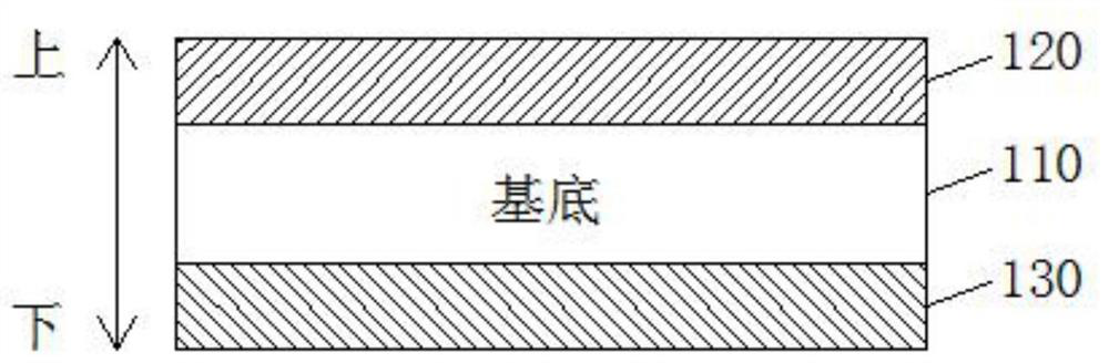
[0040] like figure 1 As shown, the present invention provides an infrared band-pass filter, which includes: a base 110 that isolates visible light from passing through infrared light, and a first structure 120 disposed on the upper surface of the base and a second structure 130 disposed on the lower surface of the substrate. The first structure includes multiple high-refractive-index layers and multiple low-refractive-index layers, and the high-refractive-index layers and the low-refractive-index layers are alternately stacked. The second structure includes multiple high-refractive index layers, multiple medium-refractive-index layers, and multiple low-refractive-index layers, and the high-refractive-index layers, the medium-refractive-index layers, and the low-refractive-index layers are alternately stacked .

[0041] In an embodiment of the present invention, the substrate is infrared glass or transparent glass coated with an absorbing material; the thickness of the substr...

Embodiment 2

[0046] Embodiment 2 is a further embodiment based on Embodiment 1. In the embodiment of the present invention, the wavelength of the passband of the infrared bandpass filter includes 850 nm. Each high refractive index layer is formed by deposition of trititanium pentoxide. Each medium index layer is formed by deposition of tantalum pentoxide. Each low refractive index layer is formed by silicon dioxide deposition. When preparing the first structure 120 and the second structure 130 , electron beam evaporation and ion-assisted deposition are both used, and a correction plate (mask) combined with an extremum method is used to control the thickness of the film layer. It should be noted that the vacuum degree and deposition rate during deposition should be controlled during preparation, and the process conditions should be optimized to obtain the best evaporated film. In the embodiment of the present invention, the substrate 110 is made of infrared glass that isolates visible li...

Embodiment 3

[0057] The substrate in the embodiment of the present invention is the same as the substrate in embodiment 2. Each high-refractive index layer is formed by depositing titanium trioxide, each medium-refractive index layer is formed by depositing tantalum pentoxide, and each low-refractive index layer is formed by depositing silicon dioxide.

[0058] In the embodiment of the present invention, the total number of layers of the anti-reflection structure layer is 4 layers, the number of each of the high refractive index layer and the low refractive index layer is 2 layers, and the total film thickness is 370.73 nm. Furthermore, the thickness of the high refractive index layer forming the anti-reflection structure layer is 5nm-320nm, and the thickness of the low-refraction index layer forming the anti-reflection structure layer is 5nm-280nm, the anti-reflection structure layer of this embodiment The material and thickness of each layer are shown in Table 3.

[0059] Table 3: Mater...


PUM

PropertyMeasurementUnit
Thicknessaaaaaaaaaa
Thicknessaaaaaaaaaa
Thicknessaaaaaaaaaa

Abstract

The invention provides an infrared band-pass optical filter and a sensor system, and relates to the technical field of optical filters, the infrared band-pass optical filter comprises a substrate for isolating visible light from transmitting infrared light, a first structure arranged on the upper surface of the substrate and a second structure arranged on the lower surface of the substrate; the first structure comprises a plurality of high-refractive-index layers and a plurality of low-refractive-index layers, and the high-refractive-index layers and the low-refractive-index layers are alternately stacked; the second structure includes a plurality of high refractive index layers, a plurality of medium refractive index layers, and a plurality of low refractive index layers. According to the invention, by selecting the substrate, the first structure and the second structure for isolating visible light from transmitting infrared light, when the incident angle of incident light is greater than or equal to 0 degree and less than or equal to 30 degrees, the position offset of 50% of the left transmittance of the near-infrared light band of the infrared band-pass filter is 0, the position offset of 50% of the right transmittance of the near-infrared light band of the infrared band-pass filter is less than or equal to 20nm, and the position offset of the central wavelength of the passband is less than or equal to 10nm.

Description

technical field [0001] The invention relates to the technical field of optical filters, in particular to an infrared bandpass optical filter and a sensor system. Background technique [0002] The basic requirement of an infrared bandpass filter is to have high transmittance in the passband and high light resistance outside the passband, that is, in the stopband. Among them, the OD value can be used to represent the light blocking rate of the stop band, and the larger the OD value, the higher the light blocking rate and the better the light blocking ability. In addition, for the infrared bandpass filter, when the incident angle of light changes, the central wavelength of the passband of the infrared bandpass filter will shift accordingly. In the traditional infrared bandpass filter, the position shift of 50% transmittance on the left and right sides of the infrared bandpass filter is greater than 30nm, and the position shift of the central wavelength of the passband is also ...

Claims


Application Information

Patent Timeline
IPC IPC(8): G02B5/20G02B5/22
CPCG02B5/208G02B5/201G02B5/226
Inventor 陈信源何伟峰
Owner GUANGZHOU JIAHE PHOTOELECTRIC TECH CO LTD
Why Eureka
Try Eureka