
Machining milling machine provided with rotating mechanism and machining method of machining milling machine

A technology of rotating mechanism and milling machine, applied in metal processing equipment, metal processing mechanical parts, manufacturing tools, etc., can solve the problems of low processing accuracy, low processing efficiency, long processing time, etc., to improve processing quality, improve processing efficiency, The effect of reducing processing time

Pending Publication Date: 2021-07-09
重庆贻晨兴工业设计有限责任公司
View PDF9 Cites 1 Cited by
  • Summary
  • Abstract
  • Description
  • Claims
  • Application Information

AI Technical Summary

Problems solved by technology

[0008] The present invention aims at the above-mentioned problems existing in the prior art, and provides a processing and milling machine equipped with a rotating mechanism, which is used to solve the problem that there is only one processing head in the prior art, and the processing parts can only be milled once at the same time, and the processing efficiency is low. Low, and one processing head can only perform one type of milling processing on the processing part at the same time. When the processing part needs to perform multiple types of milling processing, it is necessary to manually replace the tool and re-calibrate the tool, which is time-consuming and laborious, causing processing time. Long, low processing efficiency, low processing quality, etc., the present invention further provides a processing milling machine with a rotating mechanism and its processing method, which is used to solve the problem that the operator does not check the rotating mechanism, lifting mechanism, longitudinal movement mechanism and lateral movement mechanism, causing the tool to shake when milling the workpiece, resulting in low processing accuracy and low processing yield

Method used


Image

  • Machining milling machine provided with rotating mechanism and machining method of machining milling machine
  • Machining milling machine provided with rotating mechanism and machining method of machining milling machine
  • Machining milling machine provided with rotating mechanism and machining method of machining milling machine

Examples


Embodiment 1

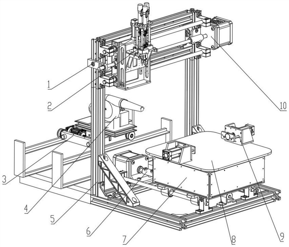
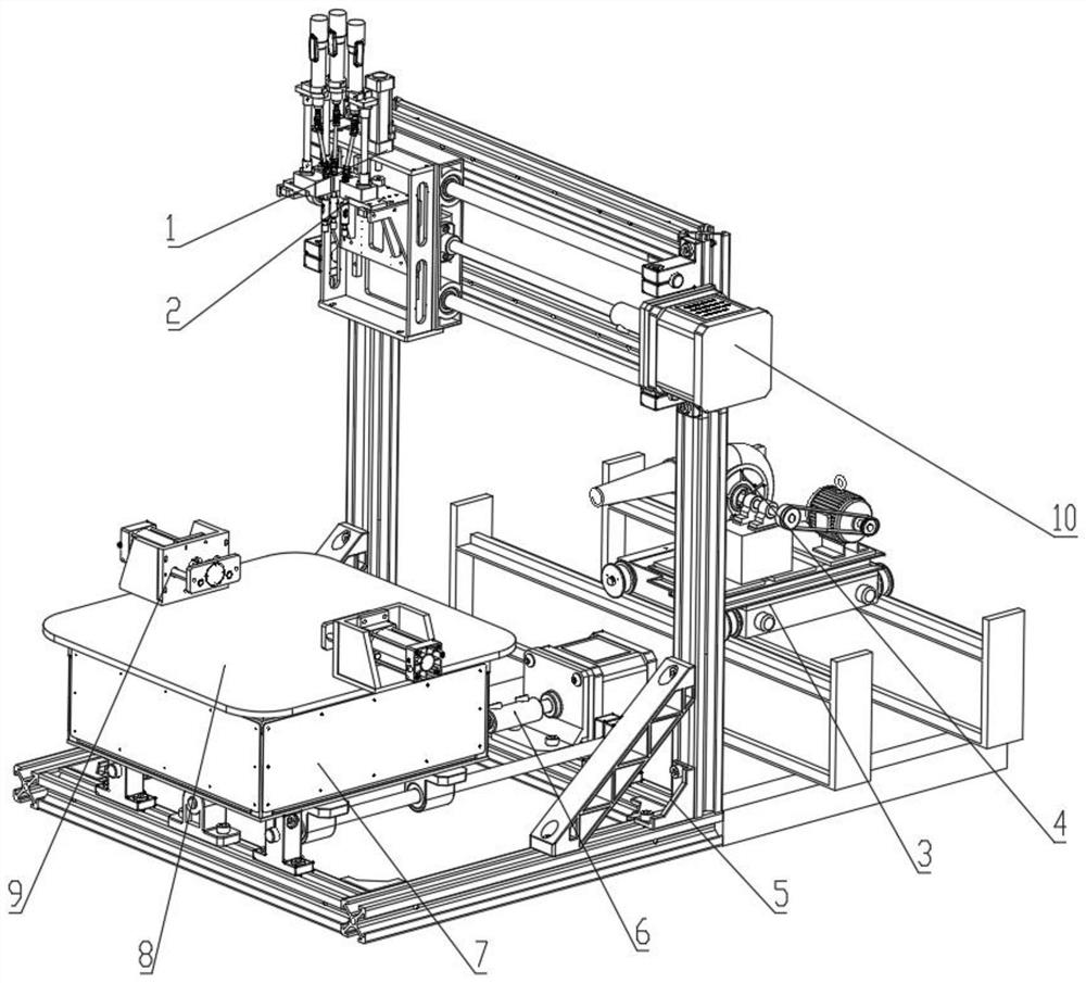
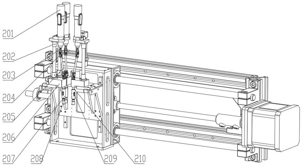
[0059] Such as Figure 1-9 As shown, a processing and milling machine provided with a rotating mechanism includes a support frame 5, a processing mechanism 2, a rotating mechanism 7, a chip removal mechanism, a placement table 8, a longitudinal movement mechanism 10, a lifting mechanism 1 and a lateral movement mechanism 6;

[0060] Lateral movement mechanism 6 is arranged on the front side middle part of support frame 5 lower ends, and rotation mechanism 7 is arranged on the upper end of lateral movement mechanism 6, and placement platform 8 is arranged on the upper end of rotation mechanism 7, and longitudinal movement mechanism 10 is arranged on the front side of support frame 5 upper ends, and lifting mechanism 1 is arranged at the front end of the longitudinal movement mechanism 10, and there are multiple processing mechanisms 2, and the multiple processing mechanisms 2 are distributed at the front end of the lifting mechanism 1 at annular intervals, and the chip removal m...

Embodiment 2

[0069] Such as Figure 1-9 As shown, a processing and milling machine provided with a rotating mechanism includes a support frame 5, a processing mechanism 2, a rotating mechanism 7, a chip removal mechanism, a placement table 8, a longitudinal movement mechanism 10, a lifting mechanism 1 and a lateral movement mechanism 6;

[0070] Lateral movement mechanism 6 is arranged on the front side middle part of support frame 5 lower ends, and rotation mechanism 7 is arranged on the upper end of lateral movement mechanism 6, and placement platform 8 is arranged on the upper end of rotation mechanism 7, and longitudinal movement mechanism 10 is arranged on the front side of support frame 5 upper ends, and lifting mechanism 1 is arranged at the front end of the longitudinal movement mechanism 10, and there are multiple processing mechanisms 2, and the multiple processing mechanisms 2 are distributed at the front end of the lifting mechanism 1 at annular intervals, and the chip removal m...


PUM


Abstract

The invention relates to the technical field of milling machines, in particular to a machining milling machine provided with a rotating mechanism. The machining milling machine comprises a supporting frame, a machining mechanism, a rotating mechanism, a chip removal mechanism, a placing table, a longitudinal moving mechanism, a lifting mechanism and a transverse moving mechanism, wherein the transverse moving mechanism is arranged in the middle of the front side of the lower end of the supporting frame, the rotating mechanism is arranged at the upper end of the transverse moving mechanism, the placing table is arranged at the upper end of the rotating mechanism, the longitudinal moving mechanism is arranged on the front side of the upper end of the supporting frame, the lifting mechanism is arranged at the front end of the longitudinal moving mechanism, the machining mechanism is arranged at the front end of the lifting mechanism, and the chip removal mechanism is arranged on the rear side of the lower end of the supporting frame. According to the machining milling machine provided with the rotating mechanism, the machining mechanism is arranged to change the milling machine into a plurality of machining devices, multiple different types of milling can be conducted on machined parts at the same time, and the rotating mechanism is arranged to drive the machined parts to rotate to conduct multi-position machining. The invention further provides a machining method of the machining milling machine provided with the rotating mechanism.

Description

technical field [0001] The invention relates to the technical field of milling machines, in particular to a processing milling machine provided with a rotating mechanism and a processing method thereof. Background technique [0002] In our country, with the continuous acceleration of economic development, various advanced high-precision equipment has been continuously introduced into the industrial field, which has brought great help to my country's industrial production. In the existing industrial production occasions, milling machines are a kind of Very common processing equipment often requires milling machines to mill workpieces. [0003] The invention with the publication number CN109079207A discloses a milling machine, which includes a fuselage, a beam arranged above the fuselage, a base arranged below the fuselage, a processing mechanism, a measuring mechanism and an azimuth control mechanism, and the driving wheel is driven by the first drive shaft Rotate, and then t...

Claims


Application Information

Patent Timeline
Patent Type & Authority Applications(China)
IPC IPC(8): B23Q1/26B23Q3/06B23Q3/00B23Q5/027B23Q5/10B23Q5/22B23Q11/00
CPCB23Q1/26B23Q3/06B23Q3/00B23Q5/027B23Q5/10B23Q5/22B23Q11/0046
Inventor 郭鑫
Owner 重庆贻晨兴工业设计有限责任公司
Learn More