Multifunctional integrated oil-mud-water separation device

A separation device, mud-water separation technology, applied in water/sludge/sewage treatment, centrifugal separation of water/sewage treatment, water pollutants, etc., can solve the problems of inconvenient sludge cleaning, large floor space, and high operating costs. Achieve the effects of easy maintenance, reduced floor space, and improved oil separation efficiency

Pending Publication Date: 2021-07-09
陕西诺金油气工程服务有限公司
View PDF0 Cites 0 Cited by
  • Summary
  • Abstract
  • Description
  • Claims
  • Application Information

AI Technical Summary

Problems solved by technology

[0004] The technical problem to be solved in the present invention is to overcome the existing defects and provide a multifunctional integrated oil sludge water separation device to solve the problem that the existing oil sludge water separation device proposed in the above background technology has a large footprint and high operating costs. And it is not convenient to clean up the separated sludge

Method used


Image

  • Multifunctional integrated oil-mud-water separation device
  • Multifunctional integrated oil-mud-water separation device
  • Multifunctional integrated oil-mud-water separation device

Examples


Embodiment 1

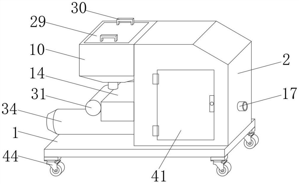
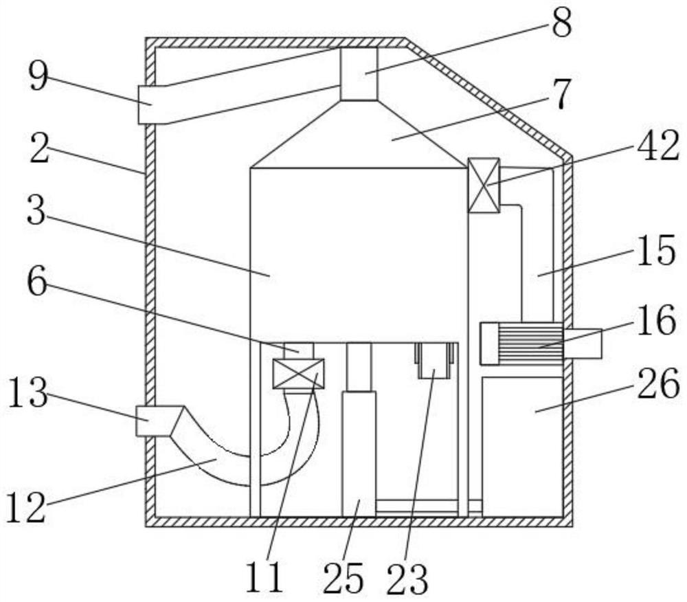
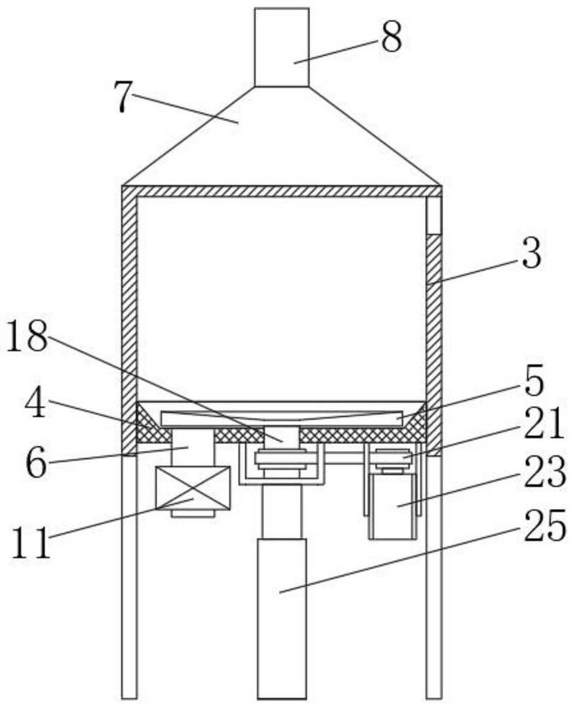
[0032] see Figure 1-3 , the present invention provides a technical solution: a multi-functional integrated oil sludge water separation device, including a bottom plate 1, the top of the bottom plate 1 is fixedly connected with a device casing 2, the inside of the device casing 2 is fixedly connected with an oil separation tank 3, and the inside of the oil separation tank 3 slides The piston 4 is connected, the inner side of the piston 4 is rotated and connected to the centrifugal turntable 5, the bottom end of the inner side of the piston 4 is fixedly connected to the sewage pipe 6, the top of the oil separation tank 3 is fixedly connected to the conical cover 7, and the top of the conical cover 7 is fixedly connected to a sink. The oil pipe 8 and the outer side of the oil collection pipe 8 are fixedly connected with an oil discharge pipe 9, and the other end of the oil discharge pipe 9 is located inside the oil distribution tank 10. By setting the device casing 2, the inside ...

Embodiment 2

[0035] see Figure 1-8, the present invention provides a technical solution: a multi-functional integrated oil sludge water separation device, including a bottom plate 1, the top of the bottom plate 1 is fixedly connected with a device casing 2, the inside of the device casing 2 is fixedly connected with an oil separation tank 3, and the inside of the oil separation tank 3 slides The piston 4 is connected, the inner side of the piston 4 is rotated and connected to the centrifugal turntable 5, the bottom end of the inner side of the piston 4 is fixedly connected to the sewage pipe 6, the top of the oil separation tank 3 is fixedly connected to the conical cover 7, and the top of the conical cover 7 is fixedly connected to a sink. The oil pipe 8 and the outer side of the oil collection pipe 8 are fixedly connected with an oil discharge pipe 9, and the other end of the oil discharge pipe 9 is located inside the oil distribution tank 10. By setting the device casing 2, the inside o...


PUM


Abstract

The invention discloses a multifunctional integrated oil-mud-water separation device, which comprises a bottom plate, wherein the top end of the bottom plate is fixedly connected with a device shell, and the interior of the device shell is fixedly connected with an oil separation tank. The device shell is arranged, the oil separation tank is arranged in the device shell, a piston is slidably connected to the inner side of the oil separation tank, sewage in the oil separation tank is centrifuged through a centrifugal rotating disc on the inner side of the piston, collection of oil in the sewage is accelerated, and finally the oil enters the oil separation tank through an oil discharge pipe under pushing of the piston, so that separation of an oil layer is accelerated, and the oil separation efficiency is improved; and an electric valve is arranged, after the oil layer is separated, the electric valve at the bottom end of a blow-off pipe is opened, sewage obtained after oil separation in the oil separation tank enters a mud-water separation box through a blow-off hose and a connecting pipe, mud and water are separated through a filter pressing membrane plate in the mud-water separation box, and then the mud-water separation effect is achieved.

Description

technical field [0001] The invention belongs to the technical field of oil sludge water separation devices, and in particular relates to a multifunctional integrated oil sludge water separation device. Background technique [0002] Oil field refers to a specific area of ​​crude oil production, sometimes a general term for oil layers accumulated underground in a specific area; among them, the oil sludge water separation and water purification treatment used in the treatment of oily sewage in oil fields and refineries are used in series by dosing and multi-stage treatment devices The purification treatment is carried out in stages, and the selected devices include separation and degreasing tanks or separation and degreasing pools, three-phase separators, air flotation devices, cyclones and filtering devices. [0003] To sum up, the existing sludge-water separation device occupies a large area, the operating cost is high, and it is not easy to clean the separated sludge. Theref...

Claims


Application Information

Patent Timeline
Patent Type & Authority Applications(China)
IPC IPC(8): C02F9/02C02F101/30
CPCC02F1/001C02F1/28C02F1/38C02F9/00C02F2101/30
Inventor 杨福涛郑德成
Owner 陕西诺金油气工程服务有限公司
Why Eureka
Try Eureka