
Coupling wave-gathering surface-shaped energy blocking synergistic device

A wave-gathering and surface-shaped technology, applied in the field of energy blocking and synergistic devices, can solve the problem of high confining pressure, achieve the effects of strong pressure bearing, increase permeability, and promote the development of reservoir fractures

Pending Publication Date: 2021-07-09
CHINA UNIV OF PETROLEUM (EAST CHINA)
View PDF0 Cites 0 Cited by
  • Summary
  • Abstract
  • Description
  • Claims
  • Application Information

AI Technical Summary

Problems solved by technology

[0006] During underground construction operations, most of the equipment is located at a depth of 700-2000 meters, so the confining pressure is relatively high

Method used


Image

  • Coupling wave-gathering surface-shaped energy blocking synergistic device
  • Coupling wave-gathering surface-shaped energy blocking synergistic device

Examples


Embodiment 1

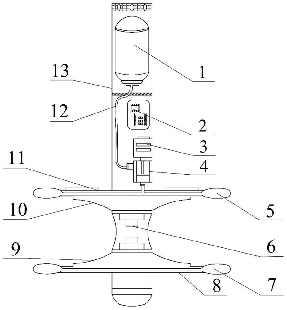
[0033] like figure 1 As shown, a coupling polywave-shaped energy barrier and synergistic device includes: a metal shell 13, a blocking part, a polywave surface, a control part, an energy converter 6, and an oil storage capsule 1; wherein,

[0034] The barrier part includes an upper isolation plate 11, a lower isolation plate 8, an upper plastic sealing cavity 5 and a lower plastic sealing cavity 7;

[0035] The control part includes a controller 2, a servo motor 3 and a pressure pump 4;

[0036] The oil storage capsule 1 is connected to the pressure pump 4 through the oil delivery pipe 12, and the pressure pump 4 is connected to the plastic sealing chamber through the oil delivery pipe 12, and the pressure pump 4 realizes the conversion of the position of the hydraulic oil in the oil storage capsule 1 and the plastic sealing chamber;

[0037] The controller 2 is connected to the servo motor 3 through a signal line, and the purpose of adjusting the internal pressure of the pla...

Embodiment 2

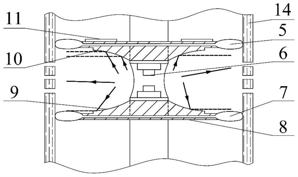
[0050] The structure of this embodiment is basically the same as that of Embodiment 1. The difference is that when the target area needs to be adjusted after the target reservoir transformation, the controller 2 sends an electrical signal to the servo motor 3; The pump 5 is working, and the hydraulic oil in the upper plastic sealing chamber 5 and the lower plastic sealing chamber 7 is transmitted to the oil storage capsule 1 through the oil delivery pipe 12; the quality of the hydraulic oil in the upper plastic sealing chamber 5 and the lower plastic sealing chamber 7 is reduced to achieve a plastic seal The outer surface of the cavity is separated from the well wall casing 14; when the pressure in the oil storage capsule 1 reaches a certain value, the servo motor 3 stops working; the position of the overall device is adjusted.

Embodiment 3

[0052] The structure of this embodiment is basically the same as that of Embodiment 1. The difference is that when some shock waves have a small exit angle and cannot reach the upper wave-condensing surface 10 or the lower wave-condensing surface 9, they directly penetrate the perforation or the well wall sleeve 14 to act on the target. reservoir.


PUM


Abstract

The invention provides a coupling wave-gathering surface-shaped energy blocking synergistic device. The synergistic device comprises a metal shell, a blocking part, a wave-gathering surface, a control part, a discharge electrode and an oil storage capsule; the blocking part comprises an upper isolation plate, a lower isolation plate, an upper plastic sealing cavity and a lower plastic sealing cavity; and the control part comprises a controller, a servo motor and a pressure pump. By means of the structure, shock waves can be increased, and the horizontal vector component of fracture development can be effectively promoted; while the loss of gas expansion potential energy is reduced, bubble pulsation is improved, and the reservoir effect is improved; and rapid adjustment of a sealing area is achieved. According to the device, the technical effect of reservoir improvement based on small explosion forms such as high-voltage pulse discharge is effectively improved, and the energy utilization rate and the reservoir improvement operation efficiency are improved.

Description

technical field [0001] The invention belongs to the field of research and development of oil and gas exploitation devices, and in particular relates to an energy barrier and synergistic device coupled with polywave surfaces. Background technique [0002] There are many types of unconventional oil and gas in my country, with great resource potential and good development prospects. Breakthroughs have been made in exploration and development in recent years. PetroChina has proven tight oil / shale oil geological reserves of 7.37×10 8 t, remaining control + predicted reserves 18.3×10 8 t, the built-up capacity is 400×10 4 t / a, but due to the harsh environment, scarcity of water resources, and complex burial geological conditions in shale oil and gas distribution areas, it is of strategic significance to innovate unconventional oil and gas recovery technologies and devices. [0003] In the development of unconventional oil and gas, it mainly includes hydraulic fracturing technol...

Claims


Application Information

Patent Timeline
Patent Type & Authority Applications(China)
IPC IPC(8): E21B43/26E21B43/263
CPCE21B43/26E21B43/263
Inventor 高崇康忠健李雷王聪龚大建
Owner CHINA UNIV OF PETROLEUM (EAST CHINA)
Learn More