

Piston ring and piston assembly
A technology of piston components and piston rings, which is applied to piston rings, engine components, machines/engines, etc., can solve the problems of low static cylinder pressure and achieve the effects of improving dynamic cylinder pressure, good stability, and simple processing technology
- Summary
- Abstract
- Description
- Claims
- Application Information
AI Technical Summary
Problems solved by technology
Method used
Image

Examples
Embodiment 1
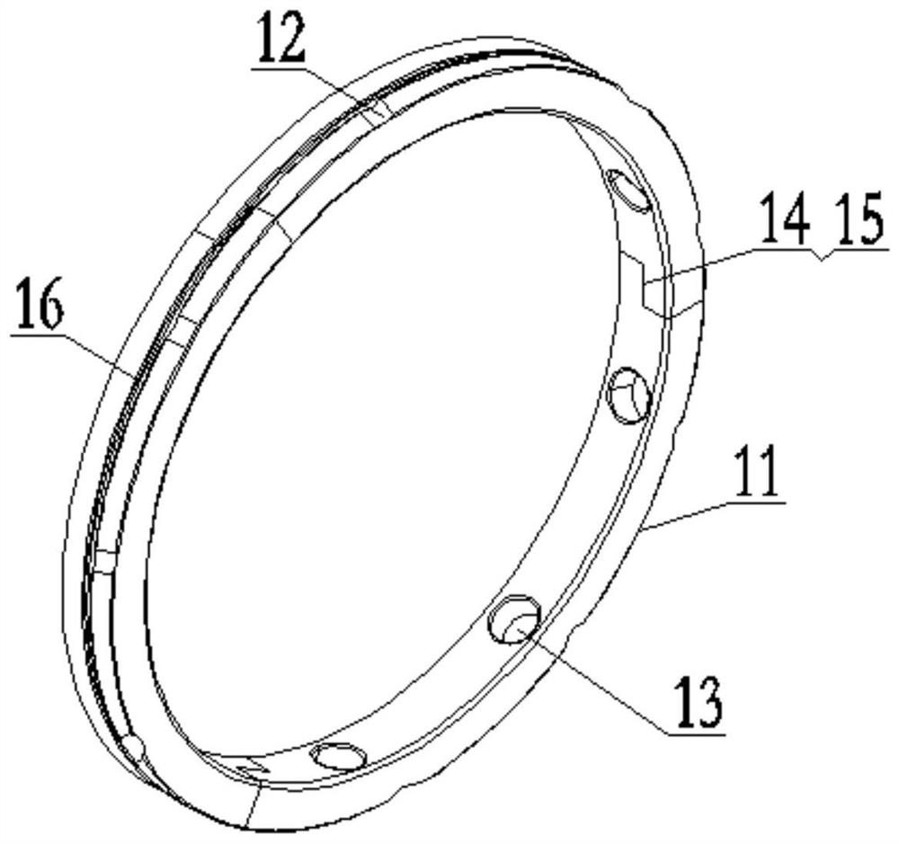
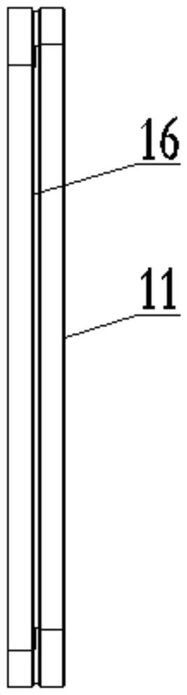
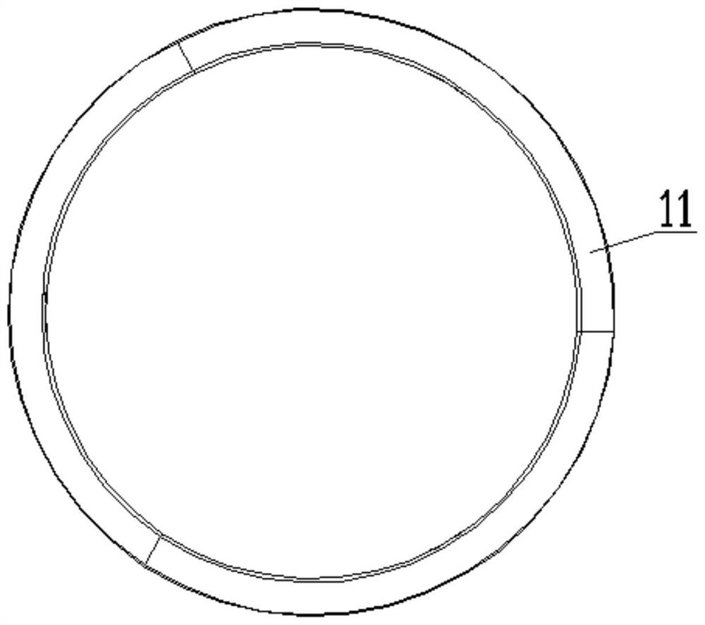
[0031] see Figure 1 to Figure 4 , a piston ring, which is an annular body 1 surrounded by three monomers 11, and the adjacent monomers 11 of the annular body 1 are overlapped with each other. One of the connecting parts of 11 is provided with a step 14, and the other connecting part is provided with a step 2 15, wherein the step 1 14 of one monomer 11 can overlap with the step 2 15 of another monomer 11 Matching, and the step surface of step one 14 and the step surface of step two 15 are all perpendicular to the axis of the piston ring. In this embodiment, the annular body 1 can be sleeved on the piston 2 and replace the sealing ring, retaining ring and oil ring of the conventional piston assembly. Two blind holes 13 are arranged on the inner wall of each monomer 11. The blind holes 13 is used to accommodate one end of the elastic element 3 . An arc-shaped groove 16 is arranged in the middle of the outer wall of the monomer 11, and the arc-shaped groove 16 is arranged circu...
Embodiment 2
[0033] see Figure 5 to Figure 7 , a piston ring, which is an annular body surrounded by three monomers 11, and the adjacent monomers 11 of the annular body enclosed together are overlapped with each other, wherein, in the same monomer 11 One of the connection parts is provided with a step 14, and the other connection part is provided with a step 2 15, wherein the step 1 14 of one monomer 11 can overlap with the step 2 15 of the other monomer 11. , and the step surface of step one 14 and the step surface of step two 15 are all perpendicular to the axis of the piston ring. In this embodiment, the annular body 1 can be sleeved on the piston and replace the sealing ring, retaining ring and oil ring of the conventional piston assembly, and three blind holes 13 are provided on the inner wall of each monomer 11, and the blind holes 13 are used for Hold elastic element 3 (elastic element 3 see Figure 10 One of the ends of the spring in). An arc-shaped groove 16 is arranged in the...
Embodiment 3
[0037] A piston ring such as Figure 8 As shown, it is formed by a plurality of monomers 11 together to form an annular body 1 suitable for the piston, and an elastic element is arranged on the inner wall of the monomer 11, and the elastic element is fastened to the blind hole on the inner wall of the monomer 11. 13, a plurality of oil grooves 12 are uniformly arranged on each single body 11, and the oil grooves 12 are arranged obliquely (obliquely with respect to the axis of the piston ring) on the outer wall of the single body 11. Arc-shaped grooves 16 are arranged on the outer walls of the cells 11 in the circumferential direction, and the arc-shaped grooves 16 on the outer walls of all the cells 11 jointly form a discontinuous annular groove, and the discontinuous area 110 is located at the connecting portion of adjacent cells 11 . The upper end of the oil groove 12 communicates with the arc groove 16 , and the lower end extends axially to the end surface of the monomer ...
PUM
 Abstract
Description
Claims
Application Information