Eureka AIR delivers breakthrough ideas for toughest innovation challenges, trusted by R&D personnel around the world.

Remote monitoring method and system for long wave time service monitoring station

A technology of remote monitoring and monitoring station, applied in the direction of instruments, character and pattern recognition, computer parts, etc., can solve the problems of low storage space utilization, waste of labor cost, wasted storage space, etc., to achieve high storage space utilization, alarm The information is clear and clear, and the effect of saving labor costs

Pending Publication Date: 2021-07-09
NAT TIME SERVICE CENT CHINESE ACAD OF SCI +1
View PDF0 Cites 0 Cited by
  • Summary
  • Abstract
  • Description
  • Claims
  • Application Information

AI Technical Summary

Problems solved by technology

[0004] (1) The nature of single and repetitive work wastes labor costs;
[0005] (2) The equipment in the monitoring station needs to run uninterruptedly for 7 x 24 hours. When the staff is not on the job, they cannot solve the problem in a timely and effective manner, which affects the monitoring quality of the long-wave timing signal;
[0006] (3) The location of the monitoring station is generally located in a relatively remote area, and the professional operation and maintenance personnel in the field are limited. If the long-wave timing monitoring station is built in the future, the number of professional operation and maintenance personnel cannot meet the requirements.
[0008] (1) The special equipment not aimed at the long-wave timing monitoring station has poor applicability;
[0009] (2) There is no classified alarm for equipment abnormalities, and the alarm clarity is insufficient;
[0010] (3) Video surveillance stores all videos, wasting storage space, and the utilization of storage space is low

Method used


Image

  • Remote monitoring method and system for long wave time service monitoring station
  • Remote monitoring method and system for long wave time service monitoring station

Examples


Embodiment Construction

[0060] In order to make the purpose, technical effects and technical solutions of the embodiments of the present invention more clear, the technical solutions in the embodiments of the present invention are clearly and completely described below in conjunction with the accompanying drawings in the embodiments of the present invention; obviously, the described embodiments It is a part of the embodiment of the present invention. Based on the disclosed embodiments of the present invention, other embodiments obtained by persons of ordinary skill in the art without making creative efforts shall all fall within the protection scope of the present invention.

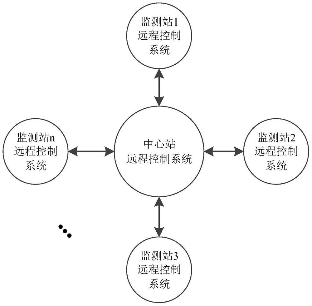
[0061] see figure 1 , a remote monitoring system for a long-wave timing monitoring station according to an embodiment of the present invention, including a central station remote control system and an outfield monitoring station remote control system, through which the operation of the equipment in the outfield monitoring stati...


PUM


Abstract

The invention discloses a remote monitoring method and system for a long wave time service monitoring station. The method comprises the following steps: acquiring monitoring station environment video information and equipment and software working condition information of an external field monitoring station; determining whether abnormal video information exists or not based on the obtained monitoring station environment video information, if yes, intercepting the abnormal video information and storing the abnormal video information, and giving out an alarm; and judging whether equipment and software are abnormal or need to be controlled based on the acquired equipment and software working condition information, if the equipment and the software are abnormal, acquiring names and state parameters of the abnormal equipment and the software and giving an alarm, and if the equipment and the software need to be controlled, controlling the equipment and the software. The long-wave time service monitoring station can be unattended, labor cost is saved, problems can be timely and effectively fed back to a central station, and continuous and reliable operation of equipment and software of the monitoring station can be guaranteed.

Description

technical field [0001] The invention belongs to the field of radio communication technology and signal measurement technology, and in particular relates to a remote monitoring method and system for a long-wave timing monitoring station. Background technique [0002] The establishment of the remote monitoring system of the long-wave timing monitoring station aims to establish an intelligent monitoring method to monitor and control the operation of the equipment in the monitoring station, the environment of the computer room and the status of the outdoor antenna, so as to realize the operation of the monitoring station equipment at the central station at any time conditions to ensure reliable and continuous operation of the equipment. [0003] At present, the long-wave timing monitoring station has not established a corresponding monitoring system, and the operation and maintenance of equipment still relies on manual inspection and control. As a result, the long-wave timing mo...

Claims


Application Information

Patent Timeline
Patent Type & Authority Applications(China)
IPC IPC(8): G06K9/00
CPCG06V20/41G06V20/52
Inventor 陈颖鸣冯平王昕黄璐希朱峰赵凡刘长虹
Owner NAT TIME SERVICE CENT CHINESE ACAD OF SCI
Why Eureka
Eureka Blog
Learn More