Unmanned aerial vehicle capable of cleaning lens

An unmanned aerial vehicle, a clean technology, applied in the field of unmanned aerial vehicles, which can solve the problems such as hindering the normal shooting of the lens, affecting the shooting process, and the lens being easily exposed to rain, dust and grass clippings, etc.

Inactive Publication Date: 2021-07-13
王志强
View PDF12 Cites 2 Cited by
  • Summary
  • Abstract
  • Description
  • Claims
  • Application Information

AI Technical Summary

Problems solved by technology

[0006] Aiming at the deficiencies of the prior art, the present invention provides a lens-cleanable unmanned aerial vehicle, which solves the problem that traditional unmanned aerial vehicles generally do not use protective covers in order to obtain high-definition picture quality when performing low-altitude operations. In winter, the lens is easily stained with rain, dust and grass clippings, which hinders the normal shooting of the lens. In winter, thin ice is more likely to form on the surface of the lens and seriously affects the shooting process. Manual cleaning is inconvenient and needs to be returned for cleaning.

Method used


Image

  • Unmanned aerial vehicle capable of cleaning lens
  • Unmanned aerial vehicle capable of cleaning lens
  • Unmanned aerial vehicle capable of cleaning lens

Examples


Embodiment 1

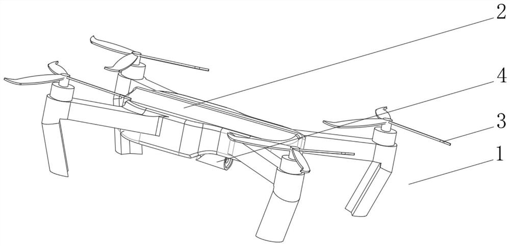
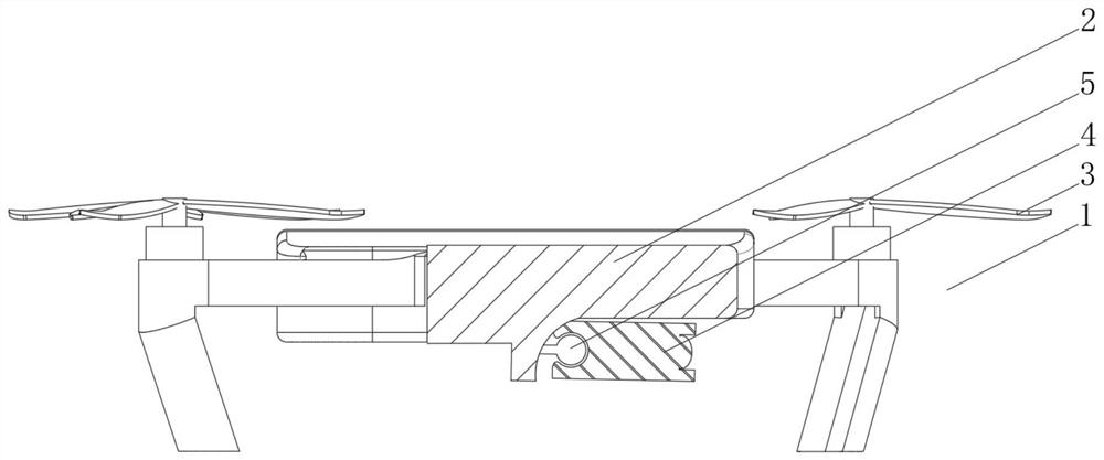
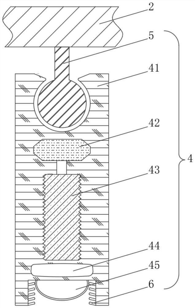
[0042] See Figure 1-4 The present invention provides a technical solution: a cleaner lens-free drone, a cleaner lens-type drone body 1 composed of a body 2, a wing 3, and an imaging mechanism 4, and the top of the body 2 is rotated by the rotating rod Turn the connection with the bottom of the wing 3, the bottom of the body 2 is rotated by the top of the imaging mechanism 4, and the imaging mechanism 4 includes a movable contact plate 41, and the internal fixation of the camera plate 41 is fixedly connected to the microfm 42, the micro blower 42 The bottom portion is connected to the air heater 43 through the gas tube, and the bottom of the air heater 43 communicates with the airbag 44 through the air supply tube, and the inside of the airbag 44 passes through the gas pipe communication with a cleaning mechanism 6, and the bottom portion of the camera plate 41 is fixedly connected to the lens 45. The debug mechanism 5 includes a linkage rod 51, the top portion of the linkage rod 5...

Embodiment 2

[0046] See Figure 1-6 Based on the first example, the present invention provides a technical solution: the cleaning mechanism 6 includes a cleaning block 61, and a gas blowing mechanism 7 is provided outside the cleaning frame 61, and the right side of the cleaning frame 61 passes through the rotary sheet and the camera 41. The internal rotation is connected, and the right side of the cleaning frame 61 is connected to the inside of the airbag 44 through the gas pipe.

[0047] The inside of the cleaning frame 61 is fixedly coupled with the expansion strip 62, and the right side of the cleaning frame 61 is fixedly connected to the push cap 63, the right side of the push blanket 63 is fixed to the inside of the camera plate 41, and the inside of the push 63 is provided with electric telescoping rod 64. The right side of the electric telescoping rod 64 is electrically connected to the external power supply.

[0048] The air blowing mechanism 7 includes the outer casing 71, the outer s...

Embodiment 3

[0052] See Figure 1-8Based on the first and examples of embodiments, the present invention provides a technical solution: the pneumatic mechanism 8 includes a pneumatic bag 81, and the outer side of the air mass 81 is provided with a first inner ring block 82 and a second inner ring block 83. The top portion of the first inner ring 82 is fixed by the bottom of the spring second inner ring block 83, and the bottom of the first inner ring 82 is fixedly connected to the first middle receipt 84, and the bottom of the first middle receipt 84 is fixedly connected. The first air ring 85.

[0053] The top of the second inner ring 83 is fixedly coupled with the second middle receipt 86, and the top of the second hinge 86 is fixedly connected to the second air ring 87, and the bottom of the first air ring 85 is fixed to the internal block 74. Connecting, the bottom of the second gas ring 87 is fixed to the inner portion of the outer block 73, and the outer side of the first middle receiving...


PUM


Abstract

The invention discloses an unmanned aerial vehicle capable of cleaning a lens, and relates to the technical field of unmanned aerial vehicles. The unmanned aerial vehicle comprises an unmanned aerial vehicle body capable of cleaning the lens composed of a vehicle body, wings and a camera shooting mechanism, the top of the vehicle body is rotationally connected with the bottoms of the wings through rotation of a rotating rod, the bottom of the vehicle body is rotationally connected with the top of the camera shooting mechanism through a debugging mechanism, the camera shooting mechanism comprises a camera shooting plate, a micro air blower is fixedly connected to the interior of the camera shooting plate, and the bottom of the micro air blower communicates with an air heater through a vent pipe. According to the unmanned aerial vehicle capable of cleaning the lens, the problems that when a traditional unmanned aerial vehicle is used, in order to obtain high-definition image quality, a protective cover is generally not adopted, during low-altitude operation, the lens is prone to being stained with rainwater, dust and grass clippings, normal shooting of the lens is hindered, thin ice is more prone to being formed on the surface of the lens in winter, the shooting process is seriously affected, manual cleaning is inconvenient, and return cleaning is needed are solved.

Description

Technical field [0001] The present invention relates to the field of drone, in particular a cleaner lens-free drone. Background technique [0002] Compared with someone driving aircraft, drones are often more suitable for those who are too "dull, dirty or danger"; drones can be divided into military and civilian use according to the application field. In terms of military, drones are divided into reconnaissance machines and targets. In civilians, drone + industry applications are truly needed for drones; currently in aerial photography, agriculture, plant protection, miniature Selfie, express delivery, disaster rescue, watching wildlife, monitoring infectious diseases, surveying, news reports, electricity patrol The application of the detection, disaster relief, film and television shooting, manufacturing romance, etc., greatly expanded the use of drone itself, and developed countries are also actively expanding industry application and development drone technology. [0003] Acco...

Claims


Application Information

Patent Timeline
IPC IPC(8): B08B5/02B08B7/00B08B13/00B64D47/08B64C27/08
CPCB08B5/02B08B7/0071B08B13/00B64D47/08B64C27/08B64U2101/30B64U10/10
Inventor 王志强
Owner 王志强
Why Eureka
Try Eureka