Supporting roller quick-changing support and quick-changing method thereof

A technology on support rolls and brackets, which is applied in the direction of metal rolling racks, metal rolling, manufacturing tools, etc., can solve the problem that the upper support roll cannot be quickly positioned and reinstalled, so as to save replacement time, simplify production, and avoid safety hidden effect

Pending Publication Date: 2021-07-13
CHONGQING IRON & STEEL CO LTD
View PDF8 Cites 1 Cited by
  • Summary
  • Abstract
  • Description
  • Claims
  • Application Information

AI Technical Summary

Problems solved by technology

[0003] In view of the above-mentioned shortcomings of the prior art, the purpose of the present invention is to provide a quick-change support for

Method used


Image

  • Supporting roller quick-changing support and quick-changing method thereof
  • Supporting roller quick-changing support and quick-changing method thereof
  • Supporting roller quick-changing support and quick-changing method thereof

Examples


Embodiment

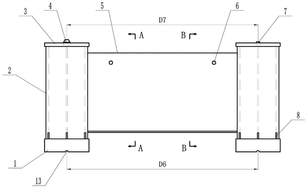
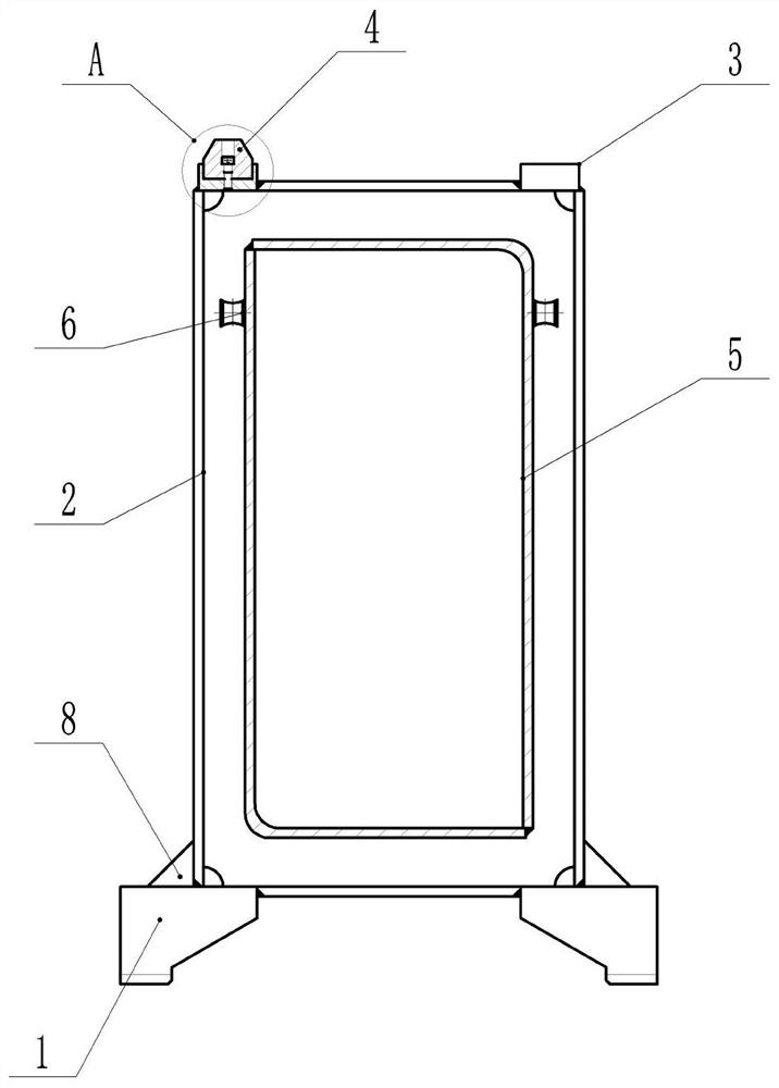
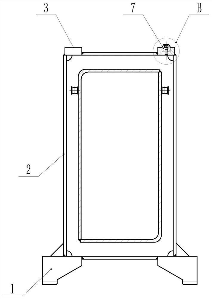
[0032] Such as Figure 1 to Figure 6 As shown, this embodiment provides a backup roller quick change bracket, including: an upper positioning assembly, a lower positioning assembly and a connecting assembly.

[0033] The lower positioning assembly includes bases 1 arranged in pairs, and a hole for positioning with the lower support roller 11 is provided on the bottom surface of the base 1. The hole is a semicircular hole 13, and the semicircular hole 13 is used to match with the positioning pin on the top surface of the lower support roller 11. .

[0034] The connecting component is arranged between the lower positioning component and the upper positioning component, and is used for connecting the upper positioning component and the lower positioning component. The connection assembly includes support frames 2 arranged in pairs. The support frames 2 are welded by six steel plates, front, rear, left, right, upper and lower. The support frames 2 are in the shape of a cuboid. A...


PUM


Abstract

The invention provides a supporting roller quick-changing support and a quick-changing method thereof. The supporting roller quick-changing method comprises the following steps that S1, a lower supporting roller is pulled out of a rack; S2, the supporting roller quick-change support is hoisted to the lower supporting roller to achieve positioning of the supporting roller quick-change support and the lower supporting roller; S3, the supporting roller quick-change support and the lower supporting roller are pushed into the rack together to realize positioning of the upper supporting roller and the supporting roller quick-change support; S4, the upper supporting roller, the supporting roller quick-change support and the lower supporting roller are pulled out of the rack together; S5, after the upper supporting roller is lifted away, a new supporting roller is lifted to the position above the supporting roller quick-change support, and the new upper supporting roller is descended so that the two ends of the new upper supporting roller can be located with the supporting roller quick-change support in sequence; S6, the new upper supporting roller returns to the rack along with the lower supporting roller and the supporting roller quick-change support, and then the new upper supporting roller is separated from the supporting roller quick-change support; and S7, the supporting roller quick-change support and the lower supporting roller are pulled out of the rack together and then lifted away from the supporting roller quick-change support, so that replacement of the upper supporting roller is completed.

Description

technical field [0001] The invention belongs to the field of continuous hot rolling, and in particular relates to a support roll quick-change bracket and a quick-change method thereof. Background technique [0002] As one of the key equipment of the hot continuous rolling mill, the back-up roll has a large diameter and heavy weight, and the replacement process of the back-up roll is cumbersome. The support rollers are tilted. At this time, the ground commanders need to repeatedly command the driving lifting operation to adjust the positioning, resulting in a long time-consuming process. And in the hoisting process, the tilt of the upper support roller is easy to injure the staff, and there is a major safety hazard. Contents of the invention [0003] In view of the above-mentioned shortcomings of the prior art, the purpose of the present invention is to provide a support roll quick change bracket for solving the problems in the prior art that the upper support roll cannot ...

Claims


Application Information

Patent Timeline
IPC IPC(8): B21B31/12
CPCB21B31/12
Inventor 贺敦军刘斌张暾何璋徐少旭谭欧王晓凤
Owner CHONGQING IRON & STEEL CO LTD
Why Eureka
Try Eureka