Evaporation treatment system for salt-containing wastewater

A technology for treating system and sewage, applied in water/sewage treatment, heating water/sewage treatment, water/sludge/sewage treatment, etc. It is impossible to realize the problems of evaporating sewage and wastewater, so as to ensure sufficient heat, stable heat input, and improve the efficiency of evaporation and drying.

Active Publication Date: 2021-07-13
CHINA ENERGY ENG GRP GUANGDONG ELECTRIC POWER DESIGN INST CO LTD
View PDF6 Cites 2 Cited by
  • Summary
  • Abstract
  • Description
  • Claims
  • Application Information

AI Technical Summary

Problems solved by technology

[0006] In order to solve the above problems, the object of the present invention is to provide an evaporation treatment system for salty waste water, to solve the problem that the input heat of evaporation of the flue gas cannot be guaranteed to be stable, and the waste water cannot be reliably evaporated; and the smoke after being treated by the drying tower After the air returns to the main flue, sludge may be formed due to the condensation of water vapor mixed with dust, which will cause the problem that the subsequent treatment process cannot operate normally

Method used


Image

  • Evaporation treatment system for salt-containing wastewater
  • Evaporation treatment system for salt-containing wastewater
  • Evaporation treatment system for salt-containing wastewater

Examples


Embodiment Construction

[0030] The specific implementation manners of the present invention will be further described in detail below in conjunction with the accompanying drawings and embodiments. The following examples are used to illustrate the present invention, but are not intended to limit the scope of the present invention.

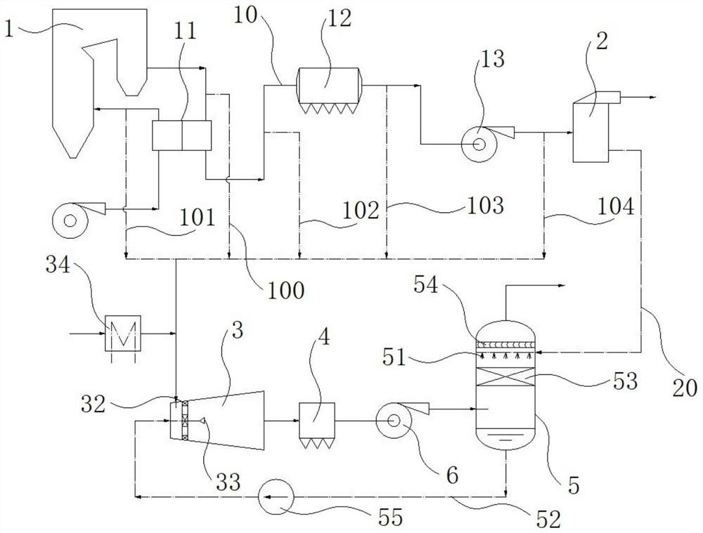
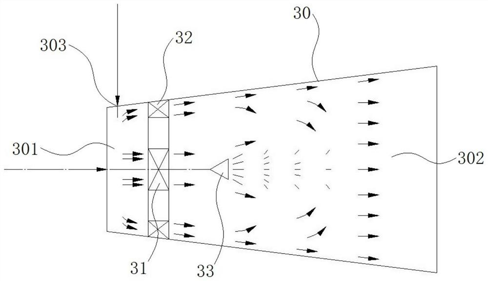
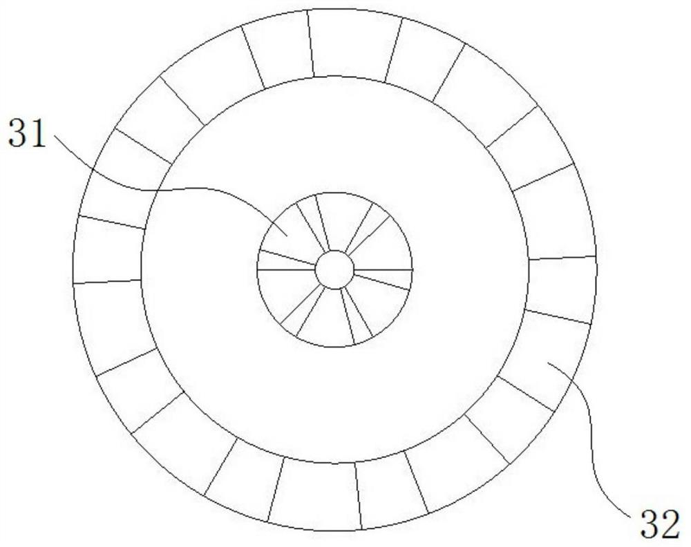
[0031] The specific embodiment of the evaporation treatment system of the salty waste water of the present invention, such as Figure 1 to Figure 4 As shown, the evaporation treatment system for salty waste water includes a boiler 1, a desulfurization tower 2, a swirling atomizing evaporator, a exhaust gas dust collector 4, and a spraying device 5. The smoke outlet of the boiler 1 and the swirling atomizing evaporator The air inlet 303 of the desulfurization tower 2 is connected to the water inlet pipeline 20 between the sewage outlet of the desulfurization tower 2 and the spray device 5, and the exhaust gas dust collector 4 is connected between the swirl atomizing evapora...


PUM


Abstract

The invention provides an evaporation treatment system for salt-containing wastewater, belonging to the field of wastewater treatment. The evaporation treatment system comprises a boiler, a desulfurization tower, a rotational-flow atomization evaporator, an exhaust gas dust remover and a spraying device, wherein a smoke outlet of the boiler communicates with an air inlet of the rotational-flow atomization evaporator, a water inlet pipeline is arranged between and connected with a sewage outlet of the desulfurization tower and the spraying device, and the exhaust gas dust remover is arranged between and connected with the rotational-flow atomization evaporator and the spraying device; the rotational-flow atomization evaporator comprises a shell, a swirler and a sprayer, the swirler communicates with a gas inlet of the rotational-flow atomization evaporator, and the gas inlet of the rotational-flow atomization evaporator is connected with a gas heater; the spraying device comprises a tank body and a spraying head, the upper part of the tank body is provided with a wet exhaust gas outlet, the lower part of the tank body is provided with a wastewater discharge outlet, and the tank body is provided with an exhaust gas inlet arranged at the lower part of the spraying head; and an exhaust port of the exhaust gas dust remover communicates with the exhaust gas inlet, and a water supply pipeline is arranged between and connected with the wastewater discharge outlet and the sprayer of the rotational-flow atomization evaporator.

Description

technical field [0001] The invention relates to the technical field of wastewater treatment, in particular to an evaporation treatment system for salty wastewater. Background technique [0002] In industrial production, salty waste water is generally produced. The infiltration process can be used to recover part of the clean water, but there is a problem of concentrated waste water discharge. The evaporation process heats the sewage and waste water, so that the water evaporates and the salt is gradually precipitated, so as to achieve the purpose of no waste water discharge. [0003] For example, the Chinese utility model patent with the authorized announcement number CN210237178U and the authorized announcement date of 2020.04.03 discloses a zero-discharge device for waste water that uses boiler hot flue gas for multi-stage evaporation, concentration and evaporation, and specifically discloses that the device uses a power plant boiler The residual heat of the flue gas heats...

Claims


Application Information

Patent Timeline
Patent Type & Authority Applications(China)
IPC IPC(8): C02F1/12C02F1/04C02F1/16
CPCC02F1/12C02F1/048C02F1/16C02F1/043C02F1/042Y02A20/141
Inventor 霍沛强樊晓茹吴阿峰张翔宇唐晖段玉燕
Owner CHINA ENERGY ENG GRP GUANGDONG ELECTRIC POWER DESIGN INST CO LTD
Why Eureka
Try Eureka