
Plasma degumming equipment for airfield runway

An airport runway and plasma technology, applied in the direction of plasma, separation method, smoke removal, etc., can solve the problems of road surface damage, exit, damage to the engine, etc., to reduce temperature shock and damage, reduce power loss, and reduce energy loss Effect

Active Publication Date: 2021-07-13
林强
View PDF10 Cites 2 Cited by
  • Summary
  • Abstract
  • Description
  • Claims
  • Application Information

AI Technical Summary

Problems solved by technology

The problem is that the metal microbeads are difficult to recover in rainy and snowy weather, and the residual metal microbeads are sucked into the engine, which will damage the engine and cause safety hazards
The problem is that under the increasingly stringent environmental protection requirements, chemical preparations will gradually withdraw from the stage of history because the impact on the surrounding environment must be considered.
[0009] The above three traditional glue removal methods are unsafe, not environmentally friendly, and cause great damage to the pavement
Plasma degumming has also appeared in the prior art, but the existing plasma degumming method consumes a lot of energy, the efficiency needs to be improved and it will damage the road surface
[0010] At present, there is a lack of a degumming method with low energy loss and high degumming efficiency in the prior art

Method used


Image

  • Plasma degumming equipment for airfield runway
  • Plasma degumming equipment for airfield runway
  • Plasma degumming equipment for airfield runway

Examples


Embodiment Construction

[0031] In order to make the technical problems, technical solutions and beneficial effects to be solved by the embodiments of the present invention clearer, the present invention will be further described in detail below in conjunction with the accompanying drawings and embodiments. It should be understood that the specific embodiments described here are only used to explain the present invention, not to limit the present invention.

[0032] It should be noted that when an element is referred to as being “fixed” or “disposed on” another element, it may be directly on the other element or be indirectly on the other element. When an element is referred to as being "connected to" another element, it can be directly connected to the other element or indirectly connected to the other element. In addition, the connection can be used for both fixing function and circuit communication function.

[0033] It is to be understood that the terms "length", "width", "top", "bottom", "front"...


PUM

PropertyMeasurementUnit
radiusaaaaaaaaaa

Abstract

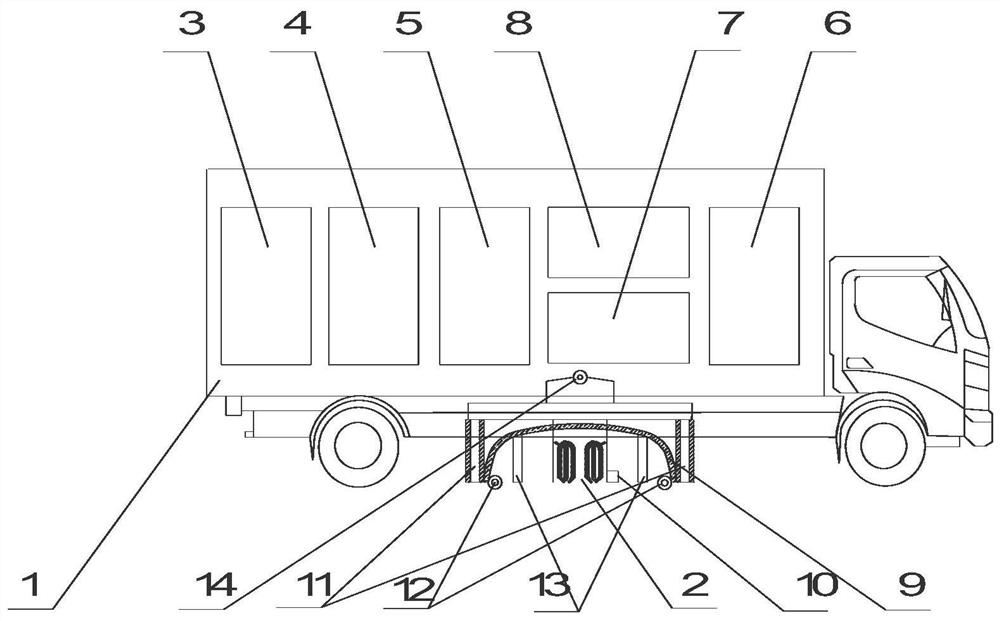
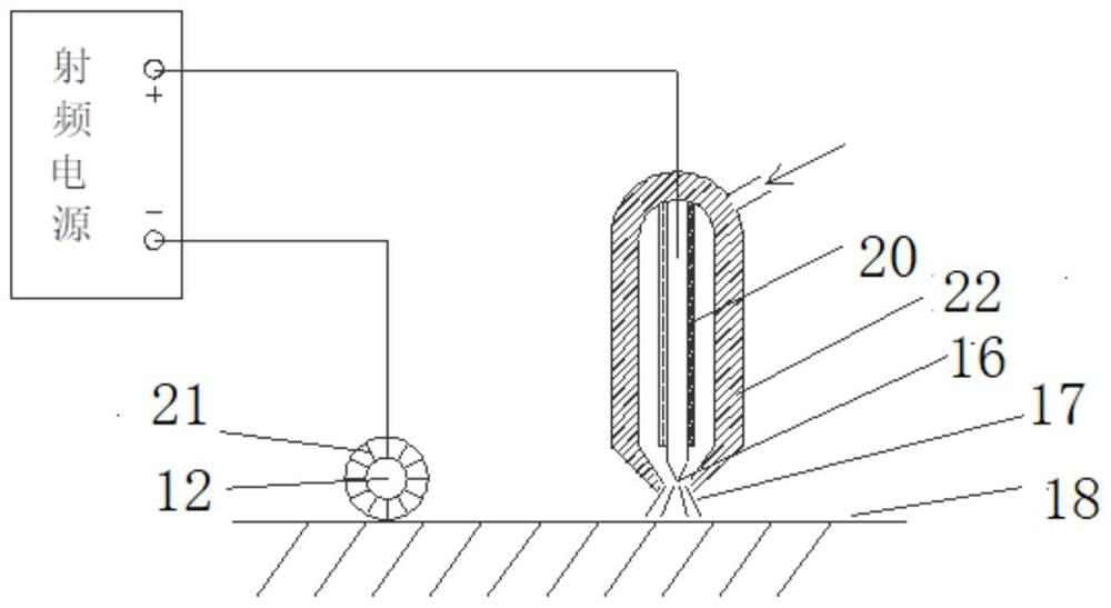
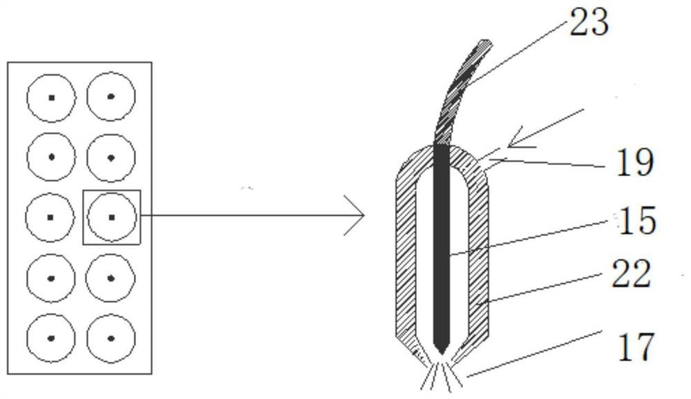
The invention provides plasma degumming equipment for an airport runway. The plasma degumming equipment comprises a carrying vehicle body, a rolling electrode mounted at the bottom of the carrying vehicle body, and a discharge electrode assembly, an oxygen generator, a radio frequency power supply and a control unit which are mounted in the carrying vehicle body; the rolling electrode is connected with the negative electrode of the radio frequency power supply, and is in rolling contact with a pavement rubber layer of the airfield runway during use, and is used for temporarily polarizing the pavement rubber layer of the airfield runway to form a temporary discharge electrode of the discharge electrode assembly; the discharge electrode assembly and a pavement rubber layer of the airport runway are directly coupled to discharge and excite oxygen ejected from the oxygen generator to generate high-concentration plasma, so that the pavement rubber layer is gasified; the oxygen generator is used for preparing oxygen by taking air as a raw material; the radio frequency power supply is used for providing a high-voltage and high-frequency power supply for the discharge electrode assembly; and the control unit is used for controlling the operation of the rolling electrode, the discharge electrode assembly, the oxygen generator and the radio frequency power supply. Plasma is generated through direct coupling type discharge, the glue removing efficiency is high, glue removing is thorough, and the road surface is not damaged.

Description

technical field [0001] The invention relates to the technical field of airport runway cleaning, in particular to a plasma degumming equipment for airport runways. Background technique [0002] The rubber left on the runway by aircraft take-off and landing has always been an important factor threatening the safety of aircraft take-off and landing. [0003] When aircraft tires land at high speed due to frictional contact with the surface of the runway, high temperature is caused. The high temperature causes the tire rubber to melt instantly to form a rubber melt and adhere to the texture of the runway surface. With the increase of friction times and the passage of time, the road The surface rubber layer is continuously piled up and thickened. The accumulated rubber layer reduces the friction coefficient of the runway surface and affects the braking performance of the aircraft. Especially when the road surface is wet and slippery, the viscosity of the rubber on the runway reduc...

Claims


Application Information

Patent Timeline
Patent Type & Authority Applications(China)
IPC IPC(8): E01H1/00B01D53/00B01D49/00B08B15/04H05H1/24
CPCE01H1/00B01D53/00B01D49/00B08B15/04H05H1/24
Inventor 王照洋程国勇
Owner 林强
Learn More