Wind-resistant metal roof structure and construction method thereof

A metal roofing and construction method technology, applied in the direction of roofing, roof covering, roofing using tile/slate tile, etc., can solve the problems of high requirements such as construction technology, material certification, quality control, detail node deepening, etc., to shorten the construction construction period, reduce the accuracy of installation and coordination, and cover the complete effect

Active Publication Date: 2021-07-13
CHINA RAILWAY CONSTR ENG GROUP
View PDF9 Cites 3 Cited by
  • Summary
  • Abstract
  • Description
  • Claims
  • Application Information

AI Technical Summary

Problems solved by technology

[0004] In order to solve the problem of obtaining the FM certificate of the metal roof system during the entire construction stage, the present invention has higher requirements on the construction process, material certification, quality control, detail node deepening, etc. during the construction process

Method used


Image

  • Wind-resistant metal roof structure and construction method thereof
  • Wind-resistant metal roof structure and construction method thereof
  • Wind-resistant metal roof structure and construction method thereof

Examples


Embodiment 1

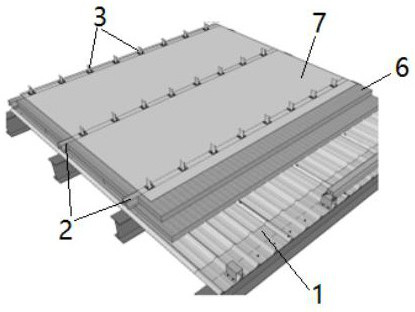
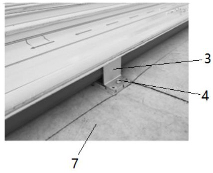
[0061] The present invention provides a wind-resistant metal roof structure, such as image 3 , Figure 4 As shown, it includes a metal roof panel and an aluminum alloy support 3, the metal roof panel is installed on the upper part of the aluminum alloy support 3, and the aluminum alloy support 3 is slidingly connected with the lining purlin 2 through a connecting mechanism 4, and the connection The mechanism 4 includes a first sliding gasket 41, a second sliding gasket 45, a compression spring 42, a connecting nut 43 and a connecting bolt 44 matched with the connecting nut 43. T-shaped hole 21, the lower part of the aluminum alloy support 3 is slidingly connected with the purlin 2 through the connecting bolt 44 and the connecting nut 43, and a first sliding gasket is installed between the lining purlin 2 and the aluminum alloy support 3 41, the lower part of the aluminum alloy support 3 is provided with a square groove 31, the width of the square groove 31 is consistent with...

Embodiment 2

[0080] like figure 1 As shown, on the basis of Example 1, the bottom plate 1 in step S1 is made of a 0.6 mm thick YX15-225-900 gray color steel press-shaped punching bottom plate 1, and the punching rate is 20% to 23%. The bottom plate 1 is processed on site in advance, and fixed on the side supporting plates of the main purlins and secondary purlins with self-tapping screws. The self-tapping screws are installed on each trough of the bottom plate 1. It needs to be installed within the scope of the purlin, and the distance from the edge of the purlin is not less than 18mm. In addition, according to the requirements of FM, the locking nails need to use Biaodi special locking nails, the models are as follows, the horizontal spacing of the locking nails is 820mm, the vertical spacing is 600mm, and the locking nails at the lap joint of the bottom plate 1 should be encrypted to 450mm. When fixing the deck board on the I-beam purlin with conventional engineering self-tapping screw...

Embodiment 3

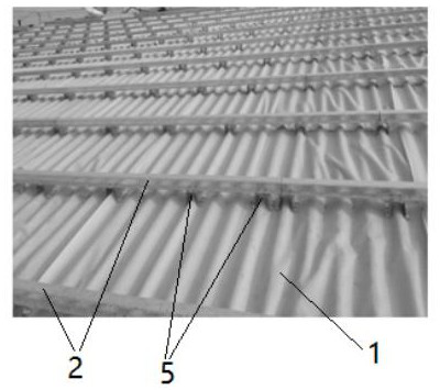
[0082] like figure 2 As shown, on the basis of Example 1, in step S2, the middle area adopts 2mm thick 25*70*70*70*25 galvanized purlins with a spacing of 1200mm, and the side area adopts 2mm thick 25*70*70*70*25 The galvanized purlins have a spacing of 900mm, and the corner area adopts 2mm thick 25*70*70*70*25 galvanized purlins with a spacing of 450mm. The spacing of the supports 5 is 1230mm, and the spacing of some areas can be Adjust as needed, the principle is no more than 1230mm, use 1070000 self-tapping screws for the connection between the support 5 and the main purlin, the quantity is according to the requirements of the node diagram, the number of self-tapping screws at each place is 4, the installation position of the self-tapping screws should be in the main purlin within the range of purlins, and the web that needs to avoid the center position; the specific method is to determine the edge and center position of the main purlin by setting out the line, and the ran...


PUM

PropertyMeasurementUnit
Thicknessaaaaaaaaaa
Horizontal spacingaaaaaaaaaa
Vertical spacingaaaaaaaaaa

Abstract

The invention provides a wind-resistant metal roof structure. The wind-resistant metal roof structure comprises a metal roof panel, an aluminum alloy support and a connecting mechanism; and the connecting mechanism comprises a first sliding sealing gasket, a second sliding sealing gasket, a compression spring, a connecting nut and a connecting bolt matched with the connecting nut. According to the wind-resistant metal roof structure, wind can be buffered to a certain extent, the risk that rigid connection easily causes damage to the metal roof panel and the aluminum alloy support is effectively avoided, and the wind resistance of the metal roof panel is improved. The invention further provides a construction method of the wind-resistant metal roof structure. The construction method comprises the following steps of S1, bottom plate installation; S2, support installation; S3, lining purlin installation; S4, construction of a PE vapor barrier film; S5, construction of the TPO waterproof coiled material; S6, aluminum alloy support installation; and S7, construction of the metal roof panel. According to the wind-resistant metal roof structure, through research and field implementation of the metal roof system construction technology under the FM certification standard, cost waste caused by a traditional construction technology is reduced, the construction period is shortened, and the construction quality is guaranteed.

Description

technical field [0001] The invention relates to the field of building construction, in particular to a wind-resistant metal roof structure. The invention also relates to a construction method of a wind-resistant metal roof structure. [0002] technical background [0003] With the rapid development of the economy, there are more and more Sino-foreign joint venture industrial projects. The roof system construction of conventional domestic industrial plant projects can be delivered to the owner after passing the inspection and acceptance of the quality and safety supervision station. However, many foreign companies are concerned about the safe use of buildings. The requirements are relatively high, which puts forward high requirements for the waterproof quality of the composite roof, the connection between the tile roof system and the metal roof system, and the wind resistance of the roof. Metal roofs are different from concrete roofs. For example, water leakage points and wea...

Claims


Application Information

Patent Timeline
IPC IPC(8): E04D11/02E04D13/16E04D3/362E04D1/34
CPCE04D11/02E04D13/16E04D3/362E04D1/34
Inventor 陈超钟世原晁毅任先松苏辉沈龙飞冯逸喆熊永志于梦奇
Owner CHINA RAILWAY CONSTR ENG GROUP
Why Eureka
Try Eureka