
Movable type high temperature coupling environment combined lifting furnace system

A mobile, high-temperature technology, used in furnaces, furnace types, furnace components, etc., can solve problems such as the inability to test the overall structure of the multi-layer frame, the inability to carry out multi-layer frame tests, and the limitation of the size of the test model. The effect of saving laboratory space and reducing steel consumption

Active Publication Date: 2021-07-13
CHINA UNIV OF MINING & TECH
View PDF7 Cites 0 Cited by
  • Summary
  • Abstract
  • Description
  • Claims
  • Application Information

AI Technical Summary

Problems solved by technology

[0003] However, there are several problems in the test process: (1) During the process of moving the test model, damage to the model and residual deformation may be caused; (2) The conventional fire test furnace can only be used for the test of component specimens, and cannot be used for multi-layer frames The test of the overall structure, and the test of a certain layer of the multi-layer frame cannot be carried out; (3) the size of the test furnace is fixed, which limits the size of the test model; (4) the combustion devices of the conventional fire test furnace are arranged on the furnace wall Above, the combustion device sprays horizontally, which is not close to the actual fire situation

Method used


Image

  • Movable type high temperature coupling environment combined lifting furnace system
  • Movable type high temperature coupling environment combined lifting furnace system
  • Movable type high temperature coupling environment combined lifting furnace system

Examples


Embodiment Construction

[0029] The following will clearly and completely describe the technical solutions in the embodiments of the present invention with reference to the accompanying drawings in the embodiments of the present invention. Obviously, the described embodiments are only some, not all, embodiments of the present invention. Based on the embodiments of the present invention, all other embodiments obtained by persons of ordinary skill in the art without making creative efforts belong to the protection scope of the present invention.

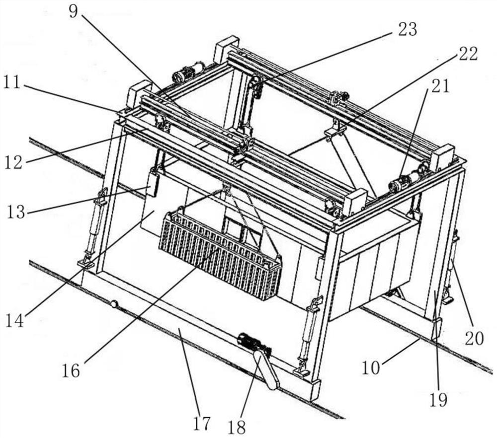
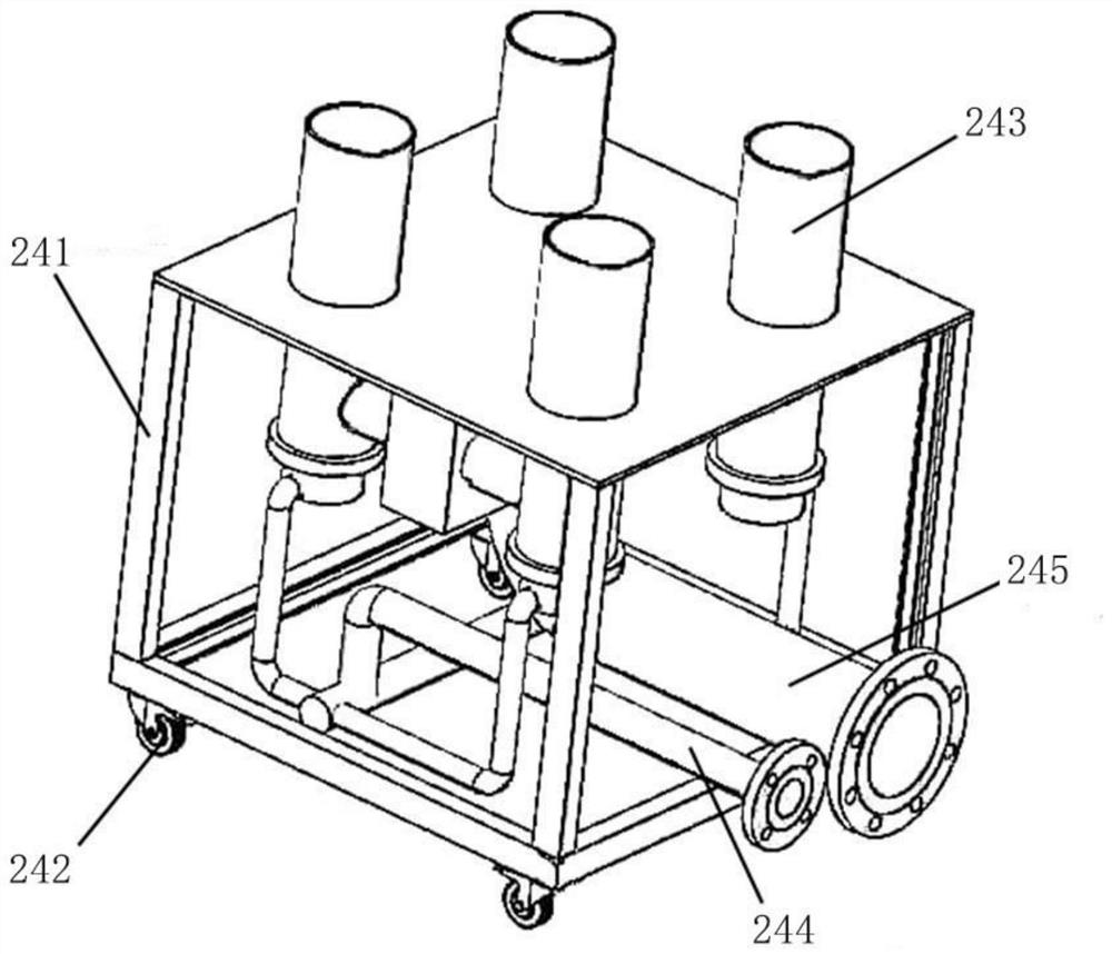
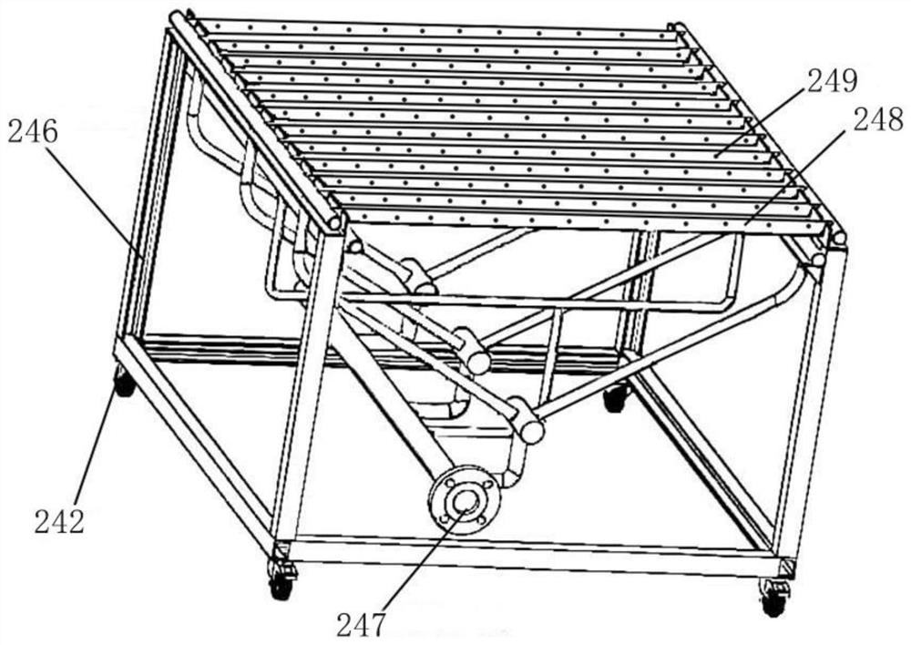
[0030] like Figure 1 to Figure 4 As shown, a mobile high-temperature coupled environment combination lifting furnace system includes a furnace body mounting frame with a combined furnace body 14 hoisted inside and capable of walking on rails 10. The upper end of the furnace body mounting frame is slidably connected with two moving The direction is vertical to the moving beam 9 of the track direction, the cross section of the moving beam 9 is a box-shaped sect...


PUM


Abstract

The invention discloses a movable type high temperature coupling environment combined lifting furnace system. The system comprises a furnace body mounting frame internally provided with a combined furnace body and capable of walking on a rail, the upper end of the furnace body mounting frame is slidably connected with two movable beams, the lower end of the furnace body mounting frame is provided with a walking device, and the middle of each movable beam is provided with a movable winch. The bottom of each movable winch is connected with an operation device in a hanging manner. The two ends of each movable beam are further slidably connected with lifting devices used for controlling the combined furnace body to ascend and descend. The combined furnace body is in a vertically-through square barrel shape and is formed by splicing a plurality of furnace body modules. A combustion device is arranged in the combined furnace body, the combustion device comprises a self-suction combustion module and a combustion-supporting combustion module, the system can be used for testing multi-layer frame test pieces on different frame layers, meanwhile, the system is suitable for the multi-layer frame test pieces with different sizes, and real fire disasters can be simulated more easily.

Description

technical field [0001] The invention relates to the technical field of fire or shock-fire coupling, in particular to a mobile high-temperature coupling environment combined lifting furnace system. Background technique [0002] At present, research on the mechanism and prevention and control of multi-disaster coupling disasters has become a major national demand. Among them, earthquakes and fires are the most frequent coupling disasters, which may lead to major accidents and disasters. At present, the main steps of earthquake-fire coupling test in China are to conduct earthquake simulation shaking table test first, and then move the model to the fire test furnace for fire test after the earthquake simulation shaking table test is completed. [0003] However, there are several problems in the test process: (1) During the process of moving the test model, damage to the model and residual deformation may be caused; (2) The conventional fire test furnace can only be used for the ...

Claims


Application Information

Patent Timeline
IPC IPC(8): F27B17/02F27D1/00F27D99/00
CPCF27B17/02F27D1/00F27D99/0033F27D2001/0079F27D2099/0098Y02P10/143
Inventor 陈伟李瑞叶继红姜健
Owner CHINA UNIV OF MINING & TECH
Learn More