Optical fiber temperature sensing Raman optical time domain reflectometer demodulation method and system

A technology of time domain reflectometer and optical fiber temperature, which is applied to thermometers, thermometers with physical/chemical changes, instruments, etc., can solve the problems of sensing optical cable demodulation temperature temperature drift, inconsistent magnification, etc., to eliminate the overall temperature drift , reduce hardware costs, and improve long-term stability

Pending Publication Date: 2021-07-13
GUANGXI NORMAL UNIV
View PDF0 Cites 0 Cited by
  • Summary
  • Abstract
  • Description
  • Claims
  • Application Information

AI Technical Summary

Problems solved by technology

The advantage of this demodulation method is that it can eliminate the influence of large loss points such as fusion splicing points on the optical fiber, but the disadvantage is that the magnifications of the two backscattered light photodetectors and the multi-stage electrical amplifiers are inconsistent, and this inconsistency will change with time. The ambient temperature changes, which will introduce a temperature drift to the demodulation temperature of the entire sensing optical cable; in addition, the entire sensing optical cable needs to be placed in a relatively stable ambient temperature to measure and store the ratio curve before application, which is very important for The application scenario of newly laying the sensing optical cable is no problem, but it is not applicable to the application scenario where the sensing optical cable has been laid and the ambient temperature of each section of the sensing optical cable is different.

Method used


Image

  • Optical fiber temperature sensing Raman optical time domain reflectometer demodulation method and system
  • Optical fiber temperature sensing Raman optical time domain reflectometer demodulation method and system
  • Optical fiber temperature sensing Raman optical time domain reflectometer demodulation method and system

Examples


Embodiment 1

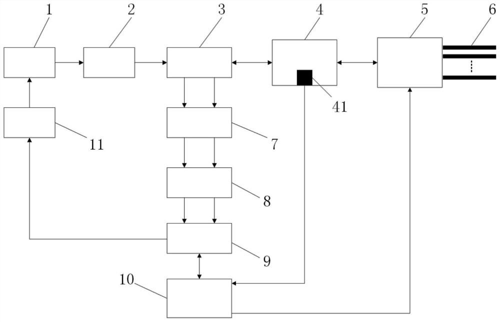
[0049] A Raman optical time domain reflectometer demodulation system for optical fiber temperature sensing, including laser 1, erbium-doped optical fiber amplifier 2, wavelength division multiplexer 3, calibration optical fiber box 4, optical switch 5, sensing optical cable 6, dual Channel APD 7, multi-stage amplifier circuit 8, acquisition card 9, processing center 10, drive circuit 11, n calibration points and m temperature detectors; the wavelength division multiplexer 3 includes COM ports, 1450 optical ports, 1550 optical ports and 1660 optical ports; the calibration optical fiber box 4 includes calibration optical fibers and a temperature sensor 41, and the acquisition card 9 includes a data acquisition card and an AD conversion circuit;

[0050] The data acquisition card 9 drives the laser 1 through the driving circuit 11 to output a laser pulse signal with a wavelength of 1550.12nm and enters the 1550nm optical port of the wavelength division multiplexer 3, and then ente...

Embodiment 2

[0088] A Raman optical time domain reflectometer demodulation system for optical fiber temperature sensing, including laser 1, erbium-doped optical fiber amplifier 2, wavelength division multiplexer 3, calibration optical fiber box 4, optical switch 5, sensing optical cable 6, dual Channel APD 7, multistage amplifier circuit 8, acquisition card 9, processing center 10 and driving circuit 11; Described wavelength division multiplexer 3 comprises COM port, 1450 optical port, 1550 optical port and 1660 optical port; Described calibration fiber Box 4 comprises calibration optical fiber and temperature sensor 41, and described acquisition card 9 comprises data acquisition card and AD conversion circuit;

[0089] The data acquisition card 9 drives the laser 1 through the driving circuit 11 to output a laser pulse signal with a wavelength of 1550.12nm and enters the 1550nm optical port of the wavelength division multiplexer 3, and then enters the calibration optical fiber from the COM...


PUM

PropertyMeasurementUnit
wavelengthaaaaaaaaaa

Abstract

The invention relates to an optical fiber temperature sensing Raman optical time domain reflectometer demodulation method and system, and the method comprises the steps that the real-time temperature of a calibration point, and the digital signal ratio of anti-Stokes light to Stokes light of each calibration point are measured; the digital signal ratio of the anti-Stokes light to the Stokes light of the calibration point at the calibration temperature is calculated, then a digital signal ratio curve of the anti-Stokes light to the Stokes light at the calibration temperature is fitted, and the digital signal ratio curve of the front end and the digital signal ratio curve of the calibration optical fiber are integrated to form a calibration curve. According to the method, the sensing optical cables at different temperatures can be well calibrated, and temperature drift caused by different amplification coefficients of anti-Stokes light and Stokes light photoelectric conversion and multi-stage amplification can be eliminated.

Description

technical field [0001] The invention belongs to the technical field of optical fiber sensing systems, and in particular relates to a Raman optical time domain reflectometer demodulation method and system for optical fiber temperature sensing. Background technique [0002] Raman optical time domain reflectometer (R-OTDR) is a distributed temperature sensing technology that combines optical time domain reflectometer (OTDR) technology with optical fiber Raman scattering effect. , continuously generating back Raman scattered light during transmission along the fiber. By detecting the change of Raman scattered light intensity along the fiber, the temperature field information along the fiber can be obtained. [0003] At present, the temperature demodulation method for the Raman optical time domain reflectometer temperature measurement system is to place the entire sensing optical cable at a certain constant temperature, and collect and save the ratio of the scattered light inten...

Claims


Application Information

Patent Timeline
Patent Type & Authority Applications(China)
IPC IPC(8): G01K11/324
CPCG01K11/32
Inventor 杨军宋树祥夏海英黄健黎标幸周龙徐隆
Owner GUANGXI NORMAL UNIV
Why Eureka
Try Eureka