Cutting die automatic production method capable of achieving continuous machining

A production method and cutting die technology, applied in simulators, instruments, computer control, etc., can solve problems such as over-cutting or under-cutting of the cone cutter, difficulty in keeping the size of the cone cutter consistent, and difficult compensation of cutter deviation, etc., to ensure continuous The effect of realizing automatic batch production, improving processing accuracy and processing efficiency

Active Publication Date: 2021-07-13
BEIJING JINGDIAO GRP CO LTD
View PDF7 Cites 0 Cited by
  • Summary
  • Abstract
  • Description
  • Claims
  • Application Information

AI Technical Summary

Problems solved by technology

In actual processing, due to the deviation between the theoretical tool and the actual tool, and the deviation value is not a fixed value, it will change with the change of the tool contact position, it is difficult to directly compensate the tool deviation in the machining path, so that the conical knife Over-cut or under-cut phenomenon occurs when processing the cutting edge and the side of the cutting edge
In order to ensure the processing accuracy of the cutting die, the current solution is to measure the conical cutter after each tool change, and edit and generate a new processing path in the CAM software according to the actual measurement results of the current tool, and then input the processing path To process in the machine tool, this method needs to stop every time the tool is changed, especially in mass production, because the size of the cone cutter is difficult to keep consistent, it is necessary to perform the above operations on each tool involved in the processing, and there is no guarantee Process efficiency and continuity of production

Method used


Image

  • Cutting die automatic production method capable of achieving continuous machining
  • Cutting die automatic production method capable of achieving continuous machining
  • Cutting die automatic production method capable of achieving continuous machining

Examples


Embodiment Construction

[0028] The present invention will be further described in detail below in conjunction with the accompanying drawings and specific embodiments.

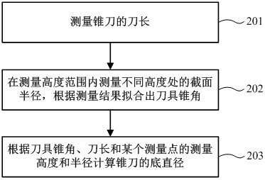
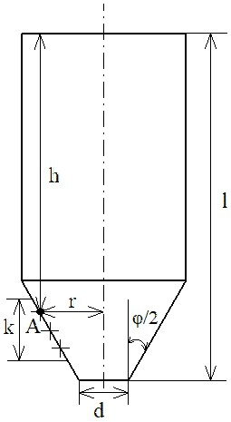
[0029] like figure 1 As shown, a kind of cutting mold automatic production method that can realize continuous processing of the present invention comprises:

[0030] Step 1, determine the number N of conical cutters used and the theoretical size parameters of each conical cutter according to the characteristics of the cutter die, edit and generate a cutter die processing program in the CAM software and input it into the CNC system of the machine tool; in the processing program, each cone The tool compensation command of the current conical tool is set before the machining path of the tool starts;

[0031] Step 2: Load the conical cutters used in the machining program into the tool magazine of the machine tool, and use the machine tool measurement system to measure the conical cutters in the tool magazine one by one, and store the mea...


PUM


Abstract

The invention belongs to the field of numerical control machining, and particularly relates to an automatic cutting die production method capable of achieving continuous machining. The method is characterized in that a numerical control machine tool on-machine measurement system is used for measuring cutters in a cutter magazine, measurement results and cutter numbers are stored in a one-to-one correspondence mode, and during cutter changing machining, a machine tool numerical control system calls the measurement results of the corresponding cutters, and combines coordinates of contact points of conical cutters and workpieces in a theoretical machining path according to the actual sizes of the conical cutters to calculate actual cutter nose point coordinates of the conical cutter, so that the theoretical cutter path is corrected to generate a new machining path for actual machining. According to the invention, the method is easy to operate, the whole process is completed in a machine tool numerical control system, repeated shutdown is not needed, production continuity is guaranteed, the machining precision and machining efficiency of the cutting die are effectively improved, and automatic batch production of the cutting die can be achieved.

Description

technical field [0001] The invention belongs to the field of numerical control processing, and in particular relates to an automatic production method of a cutting die which can realize continuous processing. Background technique [0002] The die is a commonly used forming tool in the die-cutting industry, and is usually processed by a cone knife. In actual processing, due to the deviation between the theoretical tool and the actual tool, and the deviation value is not a fixed value, it will change with the change of the tool contact position, it is difficult to directly compensate the tool deviation in the machining path, so that the conical knife Over-cutting or under-cutting occurs when processing the cutting edge and the side of the cutting edge. In order to ensure the processing accuracy of the cutting die, the current solution is to measure the conical cutter after each tool change, and edit and generate a new processing path in the CAM software according to the actua...

Claims


Application Information

Patent Timeline
Patent Type & Authority Applications(China)
IPC IPC(8): G05B19/4097
CPCG05B19/4097G05B2219/32153
Inventor 石宝光张笃光刘鑫
Owner BEIJING JINGDIAO GRP CO LTD
Why Eureka
Try Eureka