Cutting balloon catheter and cutting balloon catheter system

A technology for cutting balloon catheters and balloon catheters, which is applied in the direction of balloon catheters, catheters, surgical cutting instruments, etc., to reduce unnecessary damage, improve treatment effects, and avoid scratches

Active Publication Date: 2021-07-16
LIFETECH SCIENTIFIC (SHENZHEN) CO LTD
View PDF4 Cites 12 Cited by
  • Summary
  • Abstract
  • Description
  • Claims
  • Application Information

AI Technical Summary

Problems solved by technology

[0004] The purpose of the present invention is to at least solve the problem that the cutting balloon catheter needs to be rotated as a whole when positioning the cutting member in the blood vessel

Method used


Image

  • Cutting balloon catheter and cutting balloon catheter system
  • Cutting balloon catheter and cutting balloon catheter system
  • Cutting balloon catheter and cutting balloon catheter system

Examples


Embodiment approach 1

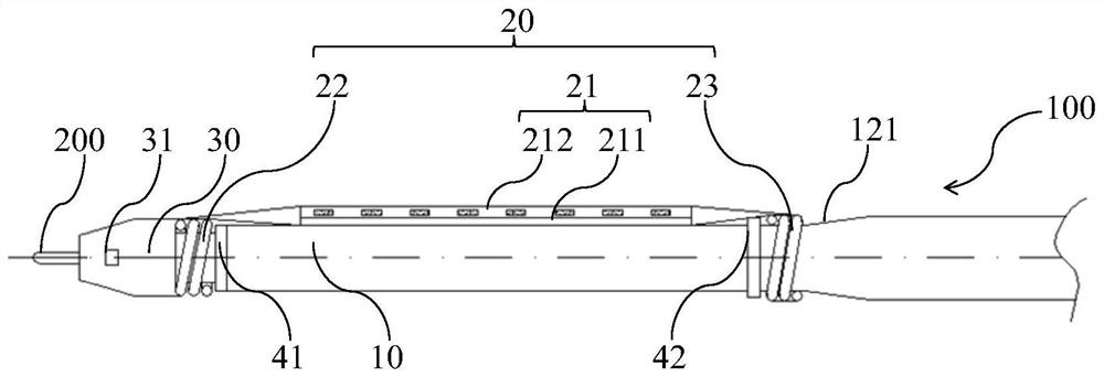
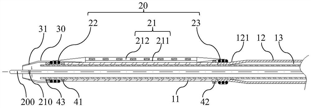
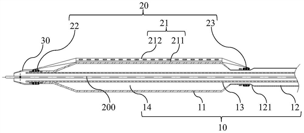
[0049] figure 1 It is a partial structural schematic diagram of the cooperation of the cutting balloon catheter 100 and the guide wire 200 in Embodiment 1 of the present invention. figure 2 for figure 1 Schematic diagram of the cross-sectional structure of the mid-cutting balloon catheter 100 cooperating with the guide wire 200 . image 3 for figure 1 Schematic diagram of the cross-sectional structure of the mid-cutting balloon catheter 100 in a pressurized state cooperating with the guide wire 200 . like figure 1 , figure 2 and image 3 As shown, the cutting balloon catheter 100 in this embodiment includes a balloon catheter 10 , a cutting assembly 20 and a transmission member 30 . The balloon catheter 10 includes a balloon body 11. The cutting assembly 20 is sleeved on the balloon catheter 10. The cutting assembly 20 is provided with a cutting unit 21 for cutting diseased tissue. The cutting unit 21 surrounds the balloon body 11 in a rotatable manner. peripheral sur...

Embodiment approach 2

[0074] Figure 9 It is a schematic diagram of the end surface structure of the cutting balloon catheter 100 in Embodiment 2 of the present invention. like Figure 9 As shown, the technical solution in this embodiment is basically the same as the solution in Embodiment 1, the difference is that the cutting units 21 in this embodiment are set in four groups, that is, four supporting parts 211 and four cutting parts 212 are respectively set, Two ends of the four supporting parts 211 are respectively connected to the first rotating member 22 and the second rotating member 23 . Of course, the cutting units 21 can also be two groups, three groups or other groups. The embodiment of the present invention does not limit the number of cutting units 21 , and those skilled in the art can flexibly choose according to needs. Specifically, when the cutting units 21 are arranged in four groups, the four groups of cutting units 21 are all arranged along the axial direction of the balloon ca...

Embodiment approach 3

[0076] Figure 10 A schematic diagram of the end surface structure of the cutting unit 21 in Embodiment 3 of the present invention. like Figure 10 As shown, the technical solution in this embodiment is basically the same as the solution in Embodiment 1, the difference is that the first middle section 2111 of the support part 211 in this embodiment is perpendicular to the axial direction of the balloon catheter 10 in a cross section that is Isosceles trapezoidal, the cross section of the cutting part 212 perpendicular to the axial direction of the balloon catheter 10 is like a figure-eight, and the cross section of the accommodating cavity 214 perpendicular to the axial direction of the balloon catheter 10 is in the shape of an inverted funnel, and the top opening of the cutting part 212 serves as Opening 2123.


PUM


Abstract

The invention relates to the field of medical instruments, in particular to a cutting balloon catheter and a cutting balloon catheter system. The cutting balloon catheter comprises a balloon catheter body, a cutting assembly and a transmission part, the balloon catheter body comprises a balloon body, the cutting assembly is arranged on the balloon catheter body in a sleeving mode, the cutting assembly is provided with at least one cutting unit used for cutting diseased tissue, the cutting units surround the peripheral face of the balloon body in a rotatable mode, the transmission part is connected with the far end of the cutting assembly, at least one metal sheet is arranged on the transmission part and can attract and be fixed to an magnetic unit under the action of the magnetic unit, and rotation of the magnetic unit drives the cutting assembly to rotate so as to directionally cut the diseased tissue. According to the cutting balloon catheter, the task of cutting the diseased tissue can be effectively completed, the balloon catheter body does not need to be rotated in the positioning process of the cutting units, scratching to blood vessels of a patient is reduced or avoided, unnecessary damage to the patient is reduced, and the treatment effect is improved.

Description

technical field [0001] The invention relates to the field of medical devices, in particular to a cutting balloon catheter and a cutting balloon catheter system. Background technique [0002] Calcification and plaques exist in peripheral and coronary vascular lesions, and drug balloons are usually used directly. When severe calcification or plaques have multiple blood vessels, these foreign bodies become obstacles to drug delivery to the intima of the blood vessels. Calcification and plaque need to be effectively cut before administration. [0003] Existing cutting balloons are divided into three types, one is a single guide wire cutting balloon (a guide wire is set on the surface of the balloon, and the guide wire is used to cut calcification and plaque after the balloon is inflated), and the other is a multi-guide wire cutting balloon. Guide wire cutting balloon (multiple guide wires are set on the surface of the balloon, and the guide wires are used to cut calcification a...

Claims


Application Information

Patent Timeline
Patent Type & Authority Applications(China)
IPC IPC(8): A61B17/3207A61B17/3209A61M25/10
CPCA61B17/3209A61B17/3207A61M25/10A61M25/0026A61M25/10181A61B2017/320741A61M2025/105
Inventor 周振标龙汉
Owner LIFETECH SCIENTIFIC (SHENZHEN) CO LTD
Why Eureka
Try Eureka