
Novel semiconductor single crystal wafer dislocation density detection corrosion tool and method

A chip and tooling technology, which is applied in the corrosion field of silicon carbide wafers, can solve the problems that the corrosion safety and stability have not been significantly improved.

Pending Publication Date: 2021-07-16
BEIJING CENTURY GOLDRAY SEMICON CO LTD
View PDF6 Cites 2 Cited by
  • Summary
  • Abstract
  • Description
  • Claims
  • Application Information

AI Technical Summary

Problems solved by technology

This device has improved the uniformity of corrosion to a certain extent, but the safety and stability of corrosion have not been significantly improved

Method used


Image

  • Novel semiconductor single crystal wafer dislocation density detection corrosion tool and method
  • Novel semiconductor single crystal wafer dislocation density detection corrosion tool and method
  • Novel semiconductor single crystal wafer dislocation density detection corrosion tool and method

Examples


Embodiment 1

[0058] Segmental lipping preheating and cooling method

[0059] Using the lift rod according to the decrease in divisions and lifting, only the wafer clamp in the tool is used.

[0060] Specific steps are as follows:

[0061] Step 1: Analyze 1.5 kgKOH to the melt to melt, keep the molten liquid temperature of about 505 ° C;

[0062] Step 2: The wafer clamp is mounted to the pullement rod, and the low heat is lowered at a height of the near liquid surface;

[0063] Step 3: The lower clamp is to enter the liquid surface at the bottom, and the wafer remains above the liquid surface, preheating for 2min;

[0064] Step 4: Continue drop to the wafer to immerse corrosion fluid, corrode 4.5 min;

[0065] Step 5: Corrosion is completed, lift the clamp to the distance liquid surface 2 cm, maintained 3.5 min;

[0066] Step 6: Rapidity to 10cm from the liquid level, cool 2min;

[0067] Step 7: Horizontal moving fixture to the cooling station, cool to 147 ° C;

[0068] Step 8: Place the fixtur...

Embodiment 2

[0072] Continuous liping and cooling method

[0073] Corrosion and improvement in the stepper motor, only the wafer clamp in the tooling.

[0074] Specific steps are as follows:

[0075] Step 1: Analyze 1.5 kgkoH to analyze the purifier to melt, keep the molten liquid temperature of about 511 ° C;

[0076] Step 2: The wafer clamp is mounted to the pull rod, and the low heat is lowered at a height of the near liquid surface;

[0077] Step 3: Control the stepper motor speed of 2.5mm / s, a falling fixture, and a preheating is 2min;

[0078] Step 4: Continuously drop the wafer and immersed in the corrosive liquid, corroded 4 min;

[0079] Step 5: Corrosion is completed, which increases the jig to 15cm from the liquid level at 3 mm / s.

[0080] Step 6: Horizontal moving fixture to the cooling station, cool to 152 ° C;

[0081] Step 7: Place the fixture and the wafer in a 90 ° C water bath and soak for 3 min.

[0082] Step 8: Take out the wafer, remove the deionized water, dry, dry, o...


PUM


Abstract

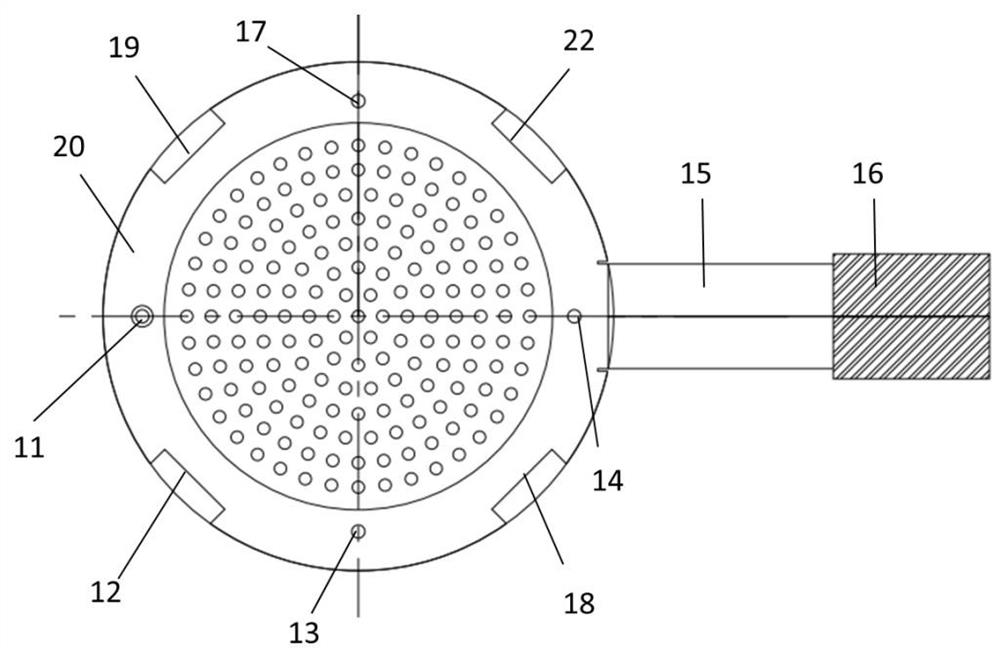
The invention discloses a silicon carbide wafer corrosion method and device. The method comprises the following steps: S1, preparing a corrosive liquid; S2, hanging a wafer clamp on a lifting hook; S3, preheating; S4, carrying out corrosion; and S5, cooling and processing a wafer. According to the corrosion method, preheating, corrosion and cooling of different time lengths can be carried out according to the size of the wafer and the estimated quality and defect density of the wafer. A lifting rod and a stepping motor are not limited to be matched with three-axis movement, and clamp movement in the up-down direction and the left-right direction is achieved. The invention also discloses a corrosion tool comprising a wafer clamp and basket combination, and the corrosion tool can be used for handheld and lifting corrosion, so that the process of obtaining a corrosion sheet is safer, and the operation difficulty is reduced. The device is simple in structure and stable in operation, the corrosion method has the advantages of being adjustable in flexibility, easy to implement and the like, and the possibility of large-size wafer fragmentation can be effectively reduced through preheating and cooling paying attention to the temperature difference.

Description

Technical field [0001] The present invention relates to etching of silicon carbide wafers, specifically a method and apparatus for corrosion by a clamp of a lifting belt wafer. Background technique [0002] As the third-generation semiconductor material, silicon is used to broadband, high-prone breakdown electric field, high thermal conductivity, radiation, corrosion resistance, etc., extensive application prospects in neighborhood of high temperature, high-power, high frequency electronic devices . [0003] The performance of silicon carbide crystals is affected by its chemical composition, structural and tissue properties. Crystal defects and their impacts are always research objects. Defects are regions where the crystals cause a deviation of the ideal structure due to thermal stress or impurities during the growth process. The chemical defects of the crystals have mainly microtubules, dislocations and small corners. The number and distribution of defects have a serious impact...

Claims


Application Information

Patent Timeline
IPC IPC(8): C30B33/10C30B29/36
CPCC30B33/10C30B29/36
Inventor 韦玉平杨丽雯陈颖超靳丽婕程章勇李百泉何丽娟张云伟李天运
Owner BEIJING CENTURY GOLDRAY SEMICON CO LTD
Learn More