
Two-section damping continuous regulating valve for shock absorber

A damping adjustment and regulating valve technology, applied in the direction of shock absorbers, shock absorbers, springs/shock absorbers, etc., can solve the problems of sudden opening and closing of the damping regulating valve port of the shock absorber, severe impact on the body, instability and other problems , to achieve the effect of fast dynamic response, strong anti-interference ability and stable damping

Active Publication Date: 2021-07-16
JIANGSU UNIV
View PDF9 Cites 2 Cited by
  • Summary
  • Abstract
  • Description
  • Claims
  • Application Information

AI Technical Summary

Problems solved by technology

This design realizes the adjustment of the damping force to a certain extent, but the adjustment of the damping force will be passively affected by the impact of the road surface. The severe impact on the body cannot truly achieve the buffering and vibration reduction effect
The Chinese Patent Publication No. CN111365402B has invented a magneto-rheological fluid two-way damping regulating valve, which uses a magnetic field to control the viscosity of the magneto-rheological fluid to adjust the resistance of the valve core when moving, and then adjusts the two damping ports through the slider. The flow area realizes the adjustment of two kinds of damping force. This design enriches the diversity of damping force adjustment to a certain extent and realizes the damping stepless adjustment. However, this design has many things to be improved: First, in a After the use time, the magnetorheological fluid will volatilize or the magnetic particles will precipitate, making the viscosity distribution of the magnetorheological fluid extremely uneven, so the movement of the valve core is easily affected by the viscosity of the magnetorheological fluid and the working pressure of the external oil chamber. This phenomenon will lead to the unstable opening state of the damping valve port, and the damping adjustment valve port of the shock absorber is prone to "sudden opening and closing" phenomenon; second, the magneto-rheological fluid as the regulating medium After the shock absorber or damping valve is placed for a long time, the original magnetic field effect of the base fluid will not be eliminated immediately after the power is cut off or the current is changed, and the response characteristics of the shock absorber or damping valve will further deteriorate; thirdly, the Although the invention proposes two damping adjustment methods, the two damping adjustment methods cannot achieve active adjustment. The manual adjustment part is only used for pre-adjustment, and secondary adjustment cannot be performed after the shock absorber is sealed and sealed. Both adjustment methods cannot produce linkage adjustment effects; Fourth, the damping adjustment method proposed by the invention does not really improve the damping adjustment range of the shock absorber or damping valve, and its actual damping adjustment range is limited by the two damping adjustment methods. The limit of the smaller side of the damping adjustment range

Method used


Image

  • Two-section damping continuous regulating valve for shock absorber
  • Two-section damping continuous regulating valve for shock absorber
  • Two-section damping continuous regulating valve for shock absorber

Examples


Embodiment Construction

[0030]The present invention will be further described below in conjunction with the accompanying drawings and specific embodiments, but the protection scope of the present invention is not limited thereto.

[0031] Embodiments of the present invention are described in detail below, examples of which are shown in the drawings, wherein the same or similar reference numerals designate the same or similar elements or elements having the same or similar functions throughout. The embodiments described below by referring to the figures are exemplary and are intended to explain the present invention and should not be construed as limiting the present invention.

[0032] In describing the present invention, it is to be understood that the terms "central", "longitudinal", "transverse", "length", "width", "thickness", "upper", "lower", "axial", The orientation or positional relationship indicated by "radial", "vertical", "horizontal", "inner", "outer", etc. is based on the orientation or...


PUM


Abstract

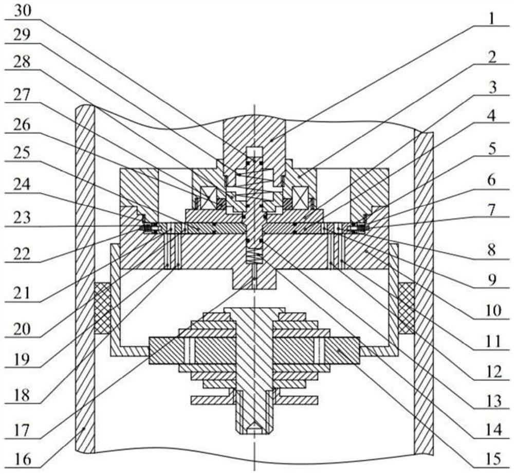
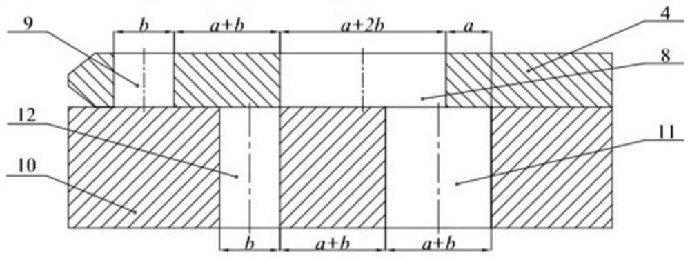
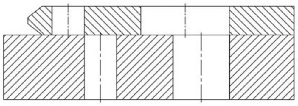
The invention provides a two-section damping continuous adjusting valve for a shock absorber. The two-section damping continuous adjusting valve comprises damping adjusting units, an adjusting valve base and a packaging valve assembly. The adjusting valve base is installed on a piston valve of the shock absorber, a plurality of damping holes are formed in the adjusting valve base, the movable damping adjusting units are installed on the adjusting valve base, damping holes corresponding to the adjusting valve base are formed in the damping adjusting units, and a main valve element of the packaging valve assembly moves up and down, so that the damping holes of the damping adjusting units partially or completely communicate with the damping holes of the adjusting valve base. According to the two-section damping continuous regulating valve for the shock absorber, continuous adjustment of damping force is achieved by adjusting the through-flow area of the first section of damping and the through-flow area of the second section of damping respectively, the damping adjustment range of the shock absorber or the damping valve is greatly expanded, and the two-section damping continuous adjusting valve has the advantages that active control is achieved, damping is steplessly adjustable, the damping adjustment process is stable, the dynamic response speed is high, and the structure is simple.

Description

technical field [0001] The invention relates to the technical field of vibration reduction of automobile suspension systems, in particular to a two-stage damping continuous regulating valve for shock absorbers. Background technique [0002] The shock absorber is an important part of the automobile suspension system. Its function is to convert the vibration energy of the vehicle body generated by the excitation of uneven road surface into heat and dissipate it into the atmospheric environment, so that the vibration of the vehicle body is attenuated. Traditional damping non-adjustable shock absorbers can no longer meet people's needs. Adjustable damping shock absorbers can switch damping according to working conditions and improve the overall performance of automobiles. This is one of the future development directions. [0003] Chinese Patent Publication No. CN109027100A discloses an oil shock absorber that realizes variable damping characteristics by changing the flow rate of...

Claims


Application Information

Patent Timeline
Patent Type & Authority Applications(China)
IPC IPC(8): F16F9/34F16F9/36F16F9/46F16K31/06F16K11/16
CPCF16F9/34F16F9/461F16F9/464F16F9/469F16F9/3405F16F9/369F16K31/0617F16K11/161
Inventor 周锐张兵虞鑫仕朱海强蔡佳敏黄华
Owner JIANGSU UNIV
Learn More