Wafer transfer box cleaning equipment and system

A technology for wafer transfer boxes and cleaning equipment, which is applied in the fields of electrical components, semiconductor/solid-state device manufacturing, circuits, etc. It can solve the problems of solid particle pollution, long maintenance time, and time difficulties, and achieve short maintenance time and less space occupation , the effect of reducing the possible pollution

Pending Publication Date: 2021-07-16
SEMTEK CORP
View PDF0 Cites 2 Cited by
  • Summary
  • Abstract
  • Description
  • Claims
  • Application Information

AI Technical Summary

Problems solved by technology

[0005] In order to avoid contamination, the cleaning time of FOUP needs to be shortened, but traditional FOUP cleaning machines are affected by the number of cleaning cycles, high complexity, high cleanliness requirements, an

Method used


Image

  • Wafer transfer box cleaning equipment and system
  • Wafer transfer box cleaning equipment and system
  • Wafer transfer box cleaning equipment and system

Examples


Embodiment Construction

[0120] According to the embodiment shown in the drawings, the detailed description is as follows:

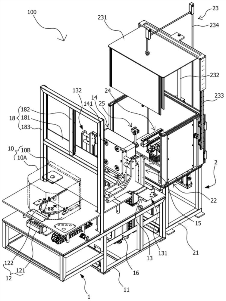
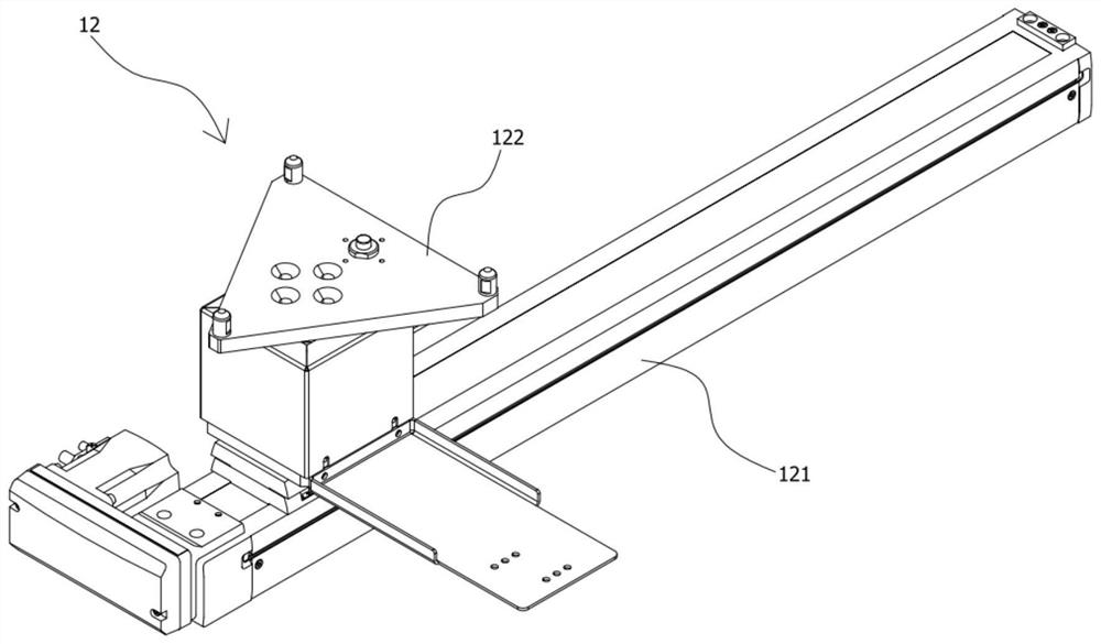
[0121] Such as Figure 1 to Figure 12 As shown, what is disclosed in the figure is a FOUP cleaning device. The cleaning device 100 can be applied to cleaning the FOUP 10. It is characterized in that: the cleaning device 100 includes at least At least one front machine platform 1 and one rear machine platform 2 located at the rear side end of said front machine platform 1; said front machine platform 1 includes a first frame body 11, a The first horizontal displacement mechanism 12 at the front side of the top end of the body 11, the flipping mechanism 13 arranged at the rear side of the top of the first frame body 11 corresponding to the first horizontal displacement mechanism 12, and the flipping mechanism 13 corresponding to the flipping mechanism at the top rear side of the first frame body 11 13 and the suction device 14 arranged at the top rear side of the first frame body...


PUM


Abstract

The invention provides wafer transfer box cleaning equipment and system which can save space, are compact in action and can avoid particle adhesion. The cleaning equipment comprises a front machine table and a rear machine table. The front machine table comprises a first frame body, a first horizontal displacement mechanism, a turnover mechanism, a suction device, a first vertical displacement mechanism, a front cleaning tank, a front cleaning device and a first isolation wall device; the rear machine table comprises a second frame body, a rear cleaning tank, a rear isolation device and a rear cleaning device; the front machine table can separate the box body from the door body, so that the door body descends, and the box body is overturned to the rear machine table for respective cleaning; the cleaning system comprises cleaning, moving, nitrogen charging and temporary storage equipment; the moving equipment can drive the wafer transfer box cleaned by the cleaning equipment to move; the nitrogen charging equipment can receive the wafer transfer box brought by the movement of the moving equipment from the cleaning equipment to charge nitrogen for the wafer transfer box; the temporary storage equipment can receive the wafer transfer box transferred by the moved equipment from the nitrogen charging equipment for temporary storage and output.

Description

technical field [0001] The invention relates to a cleaning structure and system capable of processing wafer transfer boxes and putting them into use again, in particular to a wafer transfer box cleaning equipment and system. Background technique [0002] In today's semiconductor manufacturing process, it is necessary to use a variety of methods to process the wafer. The wafer will pass through a series of process equipment and need to be transported many times during the process. Therefore, when storing and transporting the wafer, you need to pay attention not to It can be damaged by external impact, and it needs to be managed so that the surface of the wafer is not contaminated by impurities such as moisture, dust, and various organic substances. [0003] Therefore, in the process, a front opening unified pod (Front Opening Unified Pod; FOUP, or front opening integrated box) will be used to transport and store multiple wafers, which is an important carrier for transport and...

Claims


Application Information

Patent Timeline
IPC IPC(8): H01L21/67H01L21/673
CPCH01L21/67017H01L21/6704H01L21/673
Inventor 吴明芳林伯龙方子铭
Owner SEMTEK CORP
Why Eureka
Try Eureka