Heat dissipation method of server

A heat dissipation method and server technology, applied in the direction of cooling/ventilation/heating transformation, electrical components, electrical equipment structural parts, etc., can solve the problems of affecting the service life of the server, server data loss, etc., and achieve a significant cooling effect and a simple structure Effect

Active Publication Date: 2021-07-16
湖北锐火科技有限公司
View PDF8 Cites 0 Cited by
  • Summary
  • Abstract
  • Description
  • Claims
  • Application Information

AI Technical Summary

Problems solved by technology

For high-power computer rooms, heat dissipation is especially important. If the heat dissipation is no

Method used


Image

  • Heat dissipation method of server

Examples


Embodiment 1

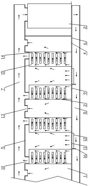
[0025] see figure 1 , the embodiment of the present invention provides a high-efficiency heat dissipation machine room, including a machine room 1 arranged in the front and rear directions, a plurality of rows of racks 2 in the machine room 1, and an air conditioner 3 that provides cold air for the machine room 1, etc., and the adjacent racks 2 are Aisle 4. The aforementioned structure is basically the same as that of the existing computer room, the difference is that:

[0026] The top and the bottom of the machine room 1 in this embodiment are respectively provided with a ceiling 5 (consistent with the conventional technology) and a floor 6 (consistent with the conventional technology, replaced with a grid plate 11 as required), and the rack 2 is arranged on the floor 6 . The ceiling 5 and the top of the machine room 1 form a return air channel 7, the floor 6 and the bottom of the machine room 1 form an air intake channel 8, and the return air channel 7 and the air intake ch...

Embodiment 2

[0034] see figure 1 , an embodiment of the present invention provides a heat dissipation method for a server, the method comprising:

[0035] Arrangement of the racks: let even racks 2 be arranged oppositely, and the return air plenum 10 on the top of the racks 2 closes the gap between the top of the racks 2 and the ceiling 5 to form a cold pool.

[0036]Sending cold air: the bottom of the rear chamber 15 of the rack 2 communicates with the air inlet channel 8 at the bottom of the machine room 1 to feed in the cold air, and the rear chambers 15 of the rack 2 on both sides of the odd number of aisles 4 are relatively arranged to form a cold pool and the odd number of passages The aisle 4 communicates with the air inlet channel 8 through the grid plate 11, the fan 12 on the lower side of the grid plate 11 blows the cold air into the cold pool, and the rear panel of the frame 2 is not closed so that the cold air in the cold pool enters the rear cavity 15 .

[0037] Server cooli...


PUM

PropertyMeasurementUnit
Widthaaaaaaaaaa
Heightaaaaaaaaaa

Abstract

The invention discloses a heat dissipation method of a server, and belongs to the technical field of data storage. The method comprises the steps that the even number of racks are oppositely arranged, and air return plenum chambers at the tops of the racks seal gaps between the tops of the racks and a ceiling; the bottoms of the rear cavities of the racks are communicated with an air inlet channel at the bottom of a machine room to introduce cold air, the rear cavities of the racks on the two sides of the odd number of passages are oppositely arranged to form a cold pool and are communicated with the air inlet channel through a grid plate, a fan on the lower side of the grid plate blows the cold air into the cold pool, and rear panels of the racks are not closed to enable the cold air in the cold pool to enter the rear cavities; and the front cavities of the racks on the two sides of the even number of passages are oppositely arranged, return air inlets are formed in the upper portions of the front cavities and communicate with the return air channels so as to send heat of the racks to the return air channels, and the tops of the front cavities of the racks communicate with the return air channels in the top of the machine room through return air plenum chambers so as to exhaust hot air. The method can be used for high power density, normal operation of the server is guaranteed, and when the air inlet temperature is 18-19 DEG C, the air return temperature is smaller than 28 DEG C.

Description

technical field [0001] The invention belongs to the technical field of data storage, and in particular relates to a heat dissipation method for a server, which can be used for high power density (greater than or equal to 10KW / rack). Background technique [0002] At present, with the development of cloud computing, big data and other technical applications, the construction requirements of data computer rooms are getting higher and higher. The data center is composed of many electronic and electromechanical facilities. In these devices, a large number of integrated circuits and electronic components are used, and they have specific requirements for the use environment, otherwise their service life and operational reliability will be affected. The mainframe of the computer system dissipates a lot of heat during operation. If the heat cannot be discharged in time, the temperature in the cabinet or the computer room will increase rapidly, which will affect the stable operation ...

Claims


Application Information

Patent Timeline
IPC IPC(8): H05K7/20
CPCH05K7/20745
Inventor 王伟
Owner 湖北锐火科技有限公司
Why Eureka
Try Eureka