Anti-coking cyclone separator capable of achieving dynamical material seal

A cyclone separator and anti-coking technology, which is applied in the direction of the cyclone device and the device where the axis of the cyclone can be reversed, etc., can solve the failure of the cyclone separator, the danger caused by the mixing of air and pyrolysis gas, and the clogging of coke blocks Legs and other problems to achieve the effect of reducing deposition and coking, ensuring long-term safe operation, and increasing flow rate

Pending Publication Date: 2021-07-20
BEIJING AEROSPACE PETROCHEM TECH & EQUIP ENG CORP LTD
View PDF0 Cites 0 Cited by
  • Summary
  • Abstract
  • Description
  • Claims
  • Application Information

AI Technical Summary

Problems solved by technology

[0004] When the existing cyclone separator is used for gas-solid separation of high-temperature pyrolysis gas, there is no anaerobic sealed environment at the material leg, and the air can easily enter the cyclone separator from the material leg, which will not only reduce the separation efficiency of the cyclone separator, but also reduce the separation efficiency of the cyclone separator. And it will introduce air to mix with pyrolysis gas to cause danger
At the same time, the dust will deposit on the outer wall of the central tube of the cyclone separator, and the coking reaction will occur with the oil mist under the long-term high temperature reaction. After a certain period of time, a large coke block will be formed on the wall. When the operating conditions fluctuate, coking The coke pieces will fall off and block the material legs, causing the cyclone separator to fail

Method used


Image

  • Anti-coking cyclone separator capable of achieving dynamical material seal
  • Anti-coking cyclone separator capable of achieving dynamical material seal
  • Anti-coking cyclone separator capable of achieving dynamical material seal

Examples


Embodiment Construction

[0028] The present invention will be described in detail below in conjunction with the accompanying drawings and specific embodiments.

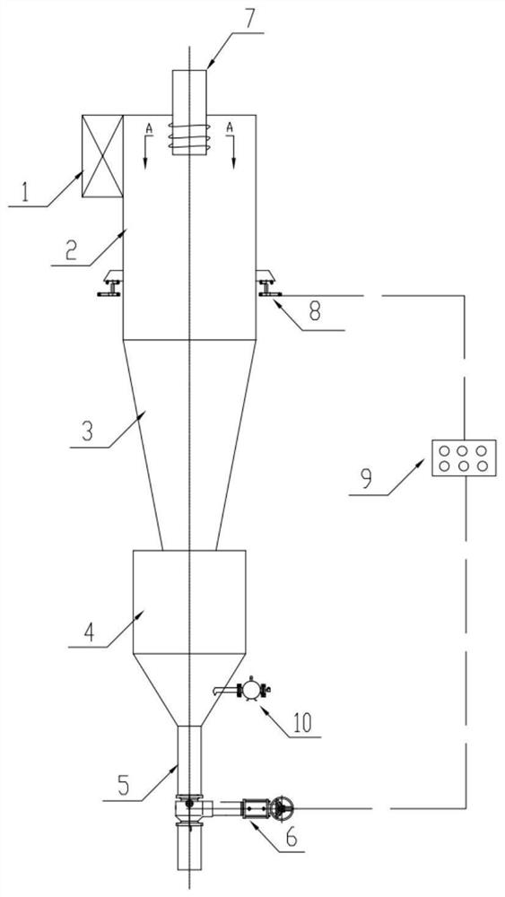
[0029] like figure 1 As shown, an anti-coking cyclone separator capable of dynamic material sealing includes a feed inlet 1, a cylinder body 2, a cone body 3, a storage bin 4, a material leg 5, a feeding controller 6, a center pipe 7, a weighing Heavy sensor 8, electric control system 9, arch breaking device 10, etc.

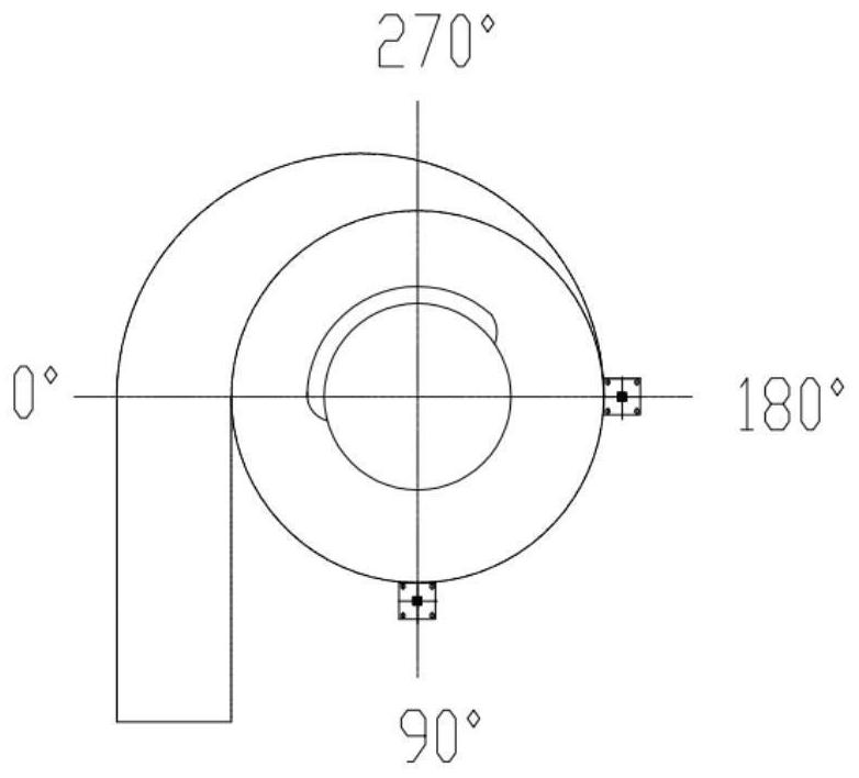
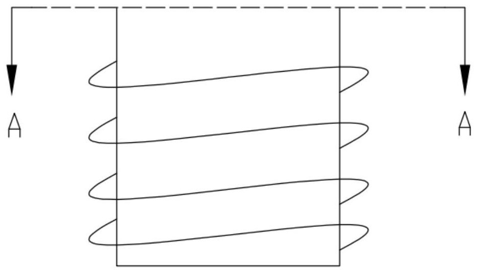
[0030] The shape of the feed inlet 1 can be circular, trapezoidal or rectangular. The feed port 1 is connected tangentially to the cylinder body 2, and the high-temperature dust-laden pyrolysis gas enters the interior of the cylinder body 2 tangentially from the feed port 1, and an external vortex is generated inside the cylinder body 2. The outer vortex is a high velocity gas flow rotating in a helical pattern from the top of the barrel 2 along the conical taper to the narrow end region at the bottom of the cone 3 . The dus...


PUM


Abstract

The invention belongs to the technical field of gas-solid separation of high-temperature pyrolysis gas, and particularly relates to an anti-coking cyclone separator capable of achieving dynamical material seal. The anti-coking cyclone separator comprises a feeding port, a barrel, a cone, a storage bin, a dipleg, a discharging controller, a central pipe, a weighing sensor, an electric control system and an arch breaking and flow aiding unblocking device, wherein the feeding port is tangentially connected with the barrel; the central pipe is arranged at the top of the barrel; the cone is connected with the barrel; the storage bin is welded to the cone; the dipleg is welded to the storage bin; the weighing sensor is placed under a lifting lug on the outer wall of the barrel and sends a weight signal to the electric control system. the electric control system sends a control signal to a discharging controller; the discharging controller has different opening degrees to control the falling speed of materials; and the arch breaking and flow aiding unblocking device is arranged on the outer wall of the storage bin. The requirement for an anaerobic or anoxic state is met through the material seal of the separator, meanwhile coking on the outer wall of the central pipe of the separator can be reduced, and the separator can operate efficiently, safely and stably for a long period under severe working conditions such as high temperature, high corrosion and strong abrasion.

Description

technical field [0001] The invention belongs to the technical field of high-temperature pyrolysis gas-solid separation, and in particular relates to an anti-coking cyclone separator capable of dynamic material sealing. Background technique [0002] The research and development and utilization of pyrolysis technology has a long history and has been widely valued in recent years. However, there are few engineering cases of large-scale operation at present. One of the technical problems that restricts the promotion of pyrolysis technology is the problem of high-temperature pyrolysis gas dust removal. The pyrolysis gas produced during the pyrolysis process has the characteristics of high temperature, oil content, corrosiveness, flammability and explosion, etc. The high temperature pyrolysis gas has complex components, which is prone to carbon deposition and coking problems, and it will also cause explosion hazards when mixed with air. [0003] At present, the technologies used f...

Claims


Application Information

Patent Timeline
Patent Type & Authority Applications(China)
IPC IPC(8): B04C5/00B04C5/14
CPCB04C5/00B04C5/14
Inventor 龚坤宋小飞张彦军许杰丁建亮赵帆杜闰萍熊哲
Owner BEIJING AEROSPACE PETROCHEM TECH & EQUIP ENG CORP LTD
Why Eureka
Try Eureka