A bare fiber grinding jig

A technology for grinding fixtures and bare optical fibers, which is used in grinding machines, manufacturing tools, grinding workpiece supports, etc., can solve the problems of easy deviation, affect the normal connection of bare optical fibers, etc., and achieve the effect of reducing loss

Active Publication Date: 2022-07-29
深圳意创通讯科技有限公司
View PDF8 Cites 2 Cited by
  • Summary
  • Abstract
  • Description
  • Claims
  • Application Information

AI Technical Summary

Problems solved by technology

[0004] In the existing polishing process of bare fiber ends, most of the fibers can only be polished one by one. However, in the actual polishing process, when each fiber is polished, it is easy to cause the end face of the bare fiber to be inclined due to fixtures, polishing equipment, and operational problems. It is easy to control the degree of deviation, which will affect the normal connection of subsequent bare optical fibers, etc.

Method used


Image

  • A bare fiber grinding jig
  • A bare fiber grinding jig
  • A bare fiber grinding jig

Examples


Embodiment Construction

[0048] The technical solutions in the embodiments of the present invention will be clearly and completely described below with reference to the accompanying drawings in the embodiments of the present invention; obviously, the described embodiments are only a part of the embodiments of the present invention, rather than all the embodiments. The embodiments of the present invention, and all other embodiments obtained by those of ordinary skill in the art without creative work, fall within the protection scope of the present invention.

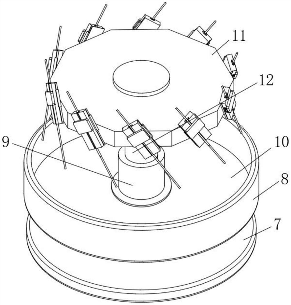
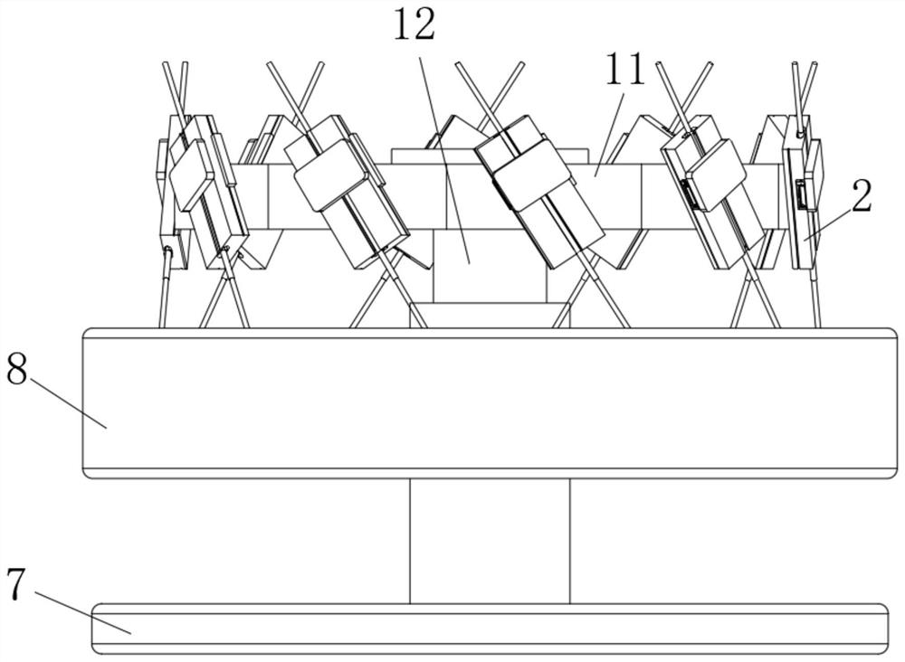
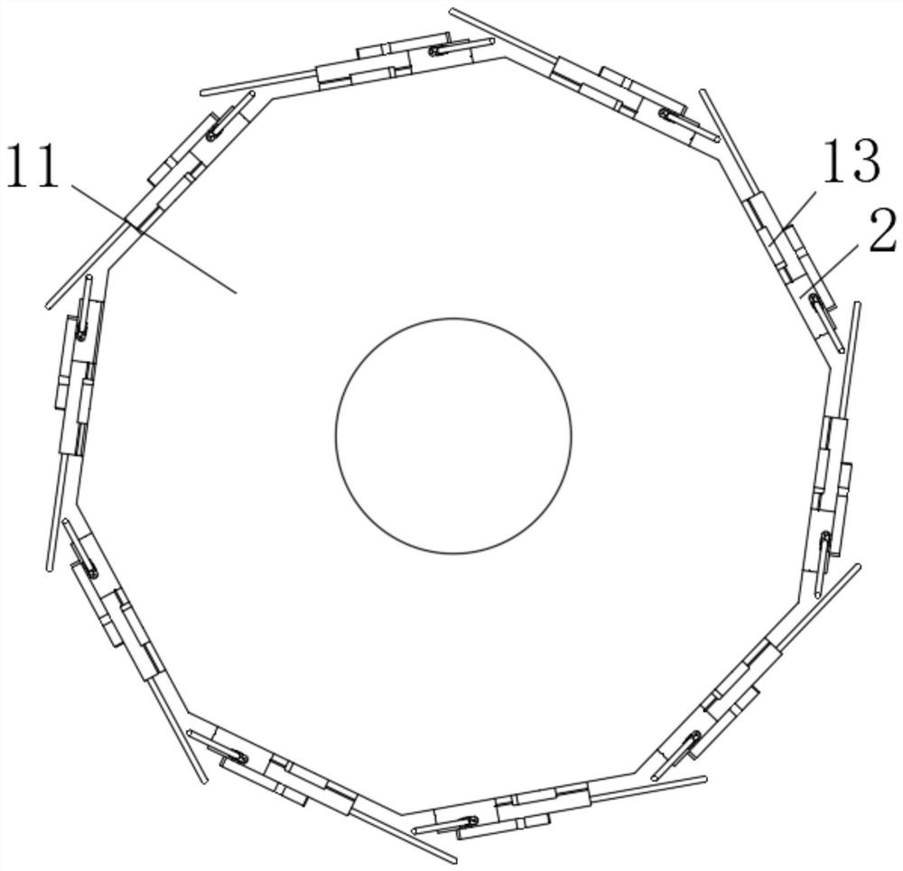
[0049] see Figure 6-8 , in the embodiment of the present invention, a kind of bare optical fiber grinding fixture, including:

[0050]The fixture seat 1, the two sides of the fixture seat 1 are provided with card grooves, the card grooves are convex grooves or dovetail grooves, and the openings of the card grooves decrease sequentially from bottom to top;

[0051] The fixture body 2 is arranged on the fixture seat 1, and the top of the fixture ...


PUM


Abstract

The invention discloses a bare optical fiber grinding fixture, which belongs to the technical field of optical fiber communication. The technical solution includes a fixture seat; a fixture body is arranged on the fixture seat, and the top of the fixture body is provided with an optical fiber groove; clamping; The mechanism is arranged on the top of the fixture seat and is located on both sides of the optical fiber slot; the accommodating groove is arranged inside the fixture seat and communicated with the optical fiber slot; the pressing cover is rotatably arranged on the optical fiber slot. The top of the main body of the clamp; wherein, in the closed state of the press cover, the two clamping mechanisms are pressed, so that the two clamping mechanisms pass through the accommodating groove and are in contact with the inside of the optical fiber groove, using In order to clamp the bare optical fiber, the present invention has better clamping effect on the optical fiber, is not easy to damage the optical fiber, and the inclination of the optical fiber end face is controllable.

Description

technical field [0001] The present invention relates to the technical field of optical fiber communication, and more particularly, to a bare optical fiber grinding fixture. Background technique [0002] In high-precision optical instruments, especially in the fields of lasers and sensors, most of them need to use optical fibers to conduct optical signal transmission, and multiple optical fibers are usually used to connect components of different instruments, and different optical fibers are connected during the docking process. , in order to maximize the signal transmission effect, it is usually used in the form of bare fiber. [0003] However, if the optical fiber is simply cut with a cleaver, it is easy to cause undesirable phenomena such as fiber edge cracking, rough end face, and optical fiber end face bevel. Therefore, the end face of the bare optical fiber needs to be ground before butting to ensure that it is smooth and clean before use. The polishing process of the...

Claims


Application Information

Patent Timeline
Patent Type & Authority Patents(China)
IPC IPC(8): B24B19/22B24B41/06G02B6/38
CPCB24B19/226B24B41/06G02B6/38
Inventor 陈敏
Owner 深圳意创通讯科技有限公司
Why Eureka
Try Eureka