Magnetic suspension pump based on hydraulic balance principle
A technology of hydraulic balance and magnetic levitation, which is applied to components, pumps, and pump devices of elastic fluid pumping devices. It can solve problems such as rotor axial impact, rotor rotation instability, and power limitation. The effect of stability, smooth water discharge and optimized structural design
- Summary
- Abstract
- Description
- Claims
- Application Information
AI Technical Summary
Problems solved by technology
Method used
Image

Examples
specific Embodiment approach 1
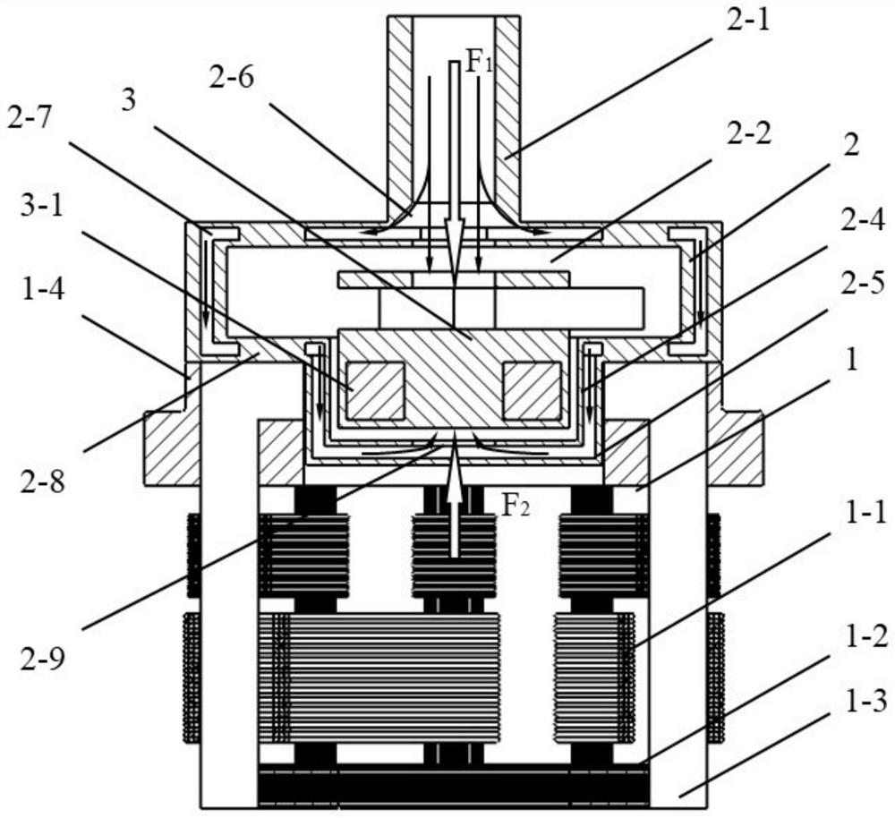
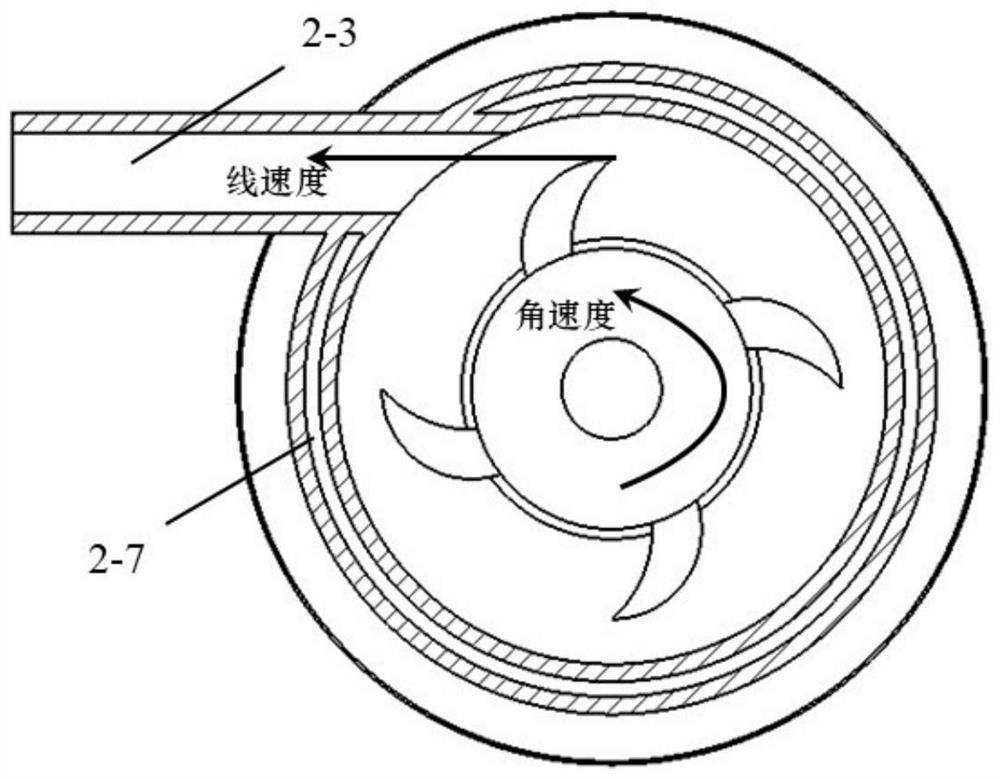
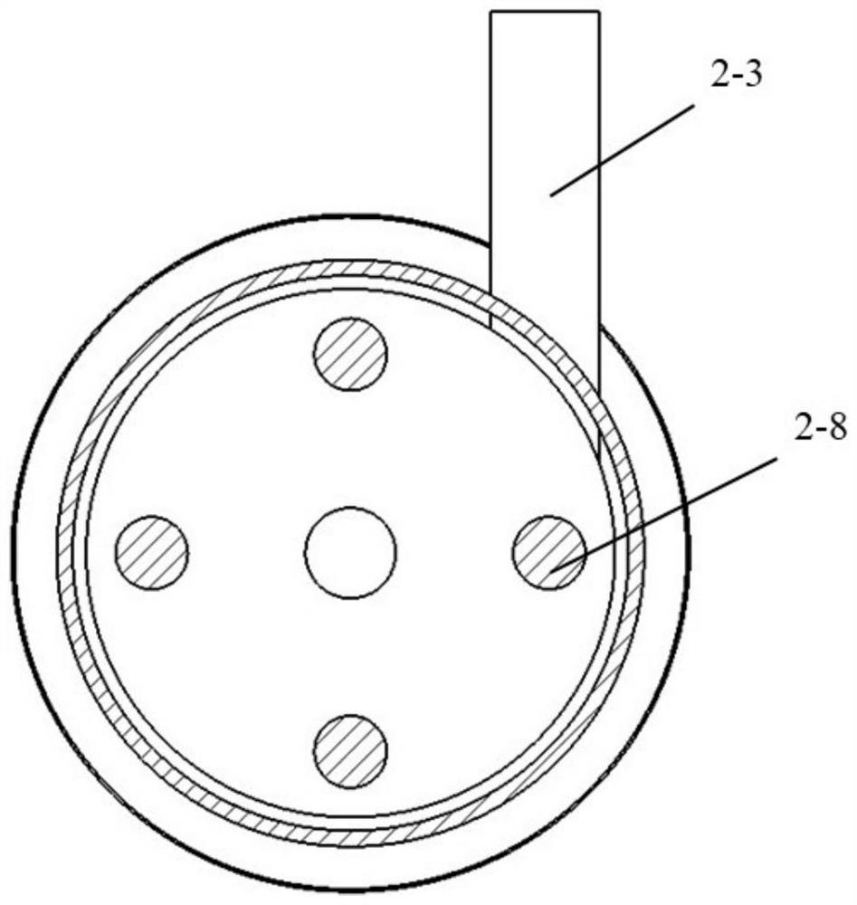
[0029] Specific implementation mode 1: internal drainage type water inlet compensation structure, combined with figure 1 , figure 2 , image 3 and Figure 4 Describe this embodiment;
[0030] Such as figure 1 As shown, the internal drainage type water inlet compensation structure includes a magnetic levitation motor 1 , a pump head 2 and an impeller system 3 . The pump head 2 is connected to the fixed frame 1-4 of the magnetic levitation motor 1 by bolts, and the impeller system 3 is suspended in the impeller cavity 2-4 of the pump head 2 by the interaction between the magnetic steel rotor 3-1 and the magnetic levitation motor 1 .
[0031] The magnetic levitation motor 1 includes a winding 1-1, a back iron 1-2, a magnetically permeable frame 1-3 and a fixed frame 1-4. The magnetic frame 1-3 is tightly connected to the back iron 1-2, the winding 1-1 is closely connected to the magnetic frame 1-3, and the fixed frame 1-4 is tightly connected to the magnetic frame 1-3. The...
specific Embodiment approach 2
[0036] Specific implementation mode two: the single motor form of the two-way water inlet compensation structure, combined with Figure 5 , Figure 6 , Figure 7 Explain the implementation mode.
[0037] Such as Figure 5As shown, the difference between the single motor form of the two-way water inlet compensation structure and the internal drainage type water inlet compensation structure of the specific embodiment 1 is that the pump head 2 of the single motor form is designed with an auxiliary water inlet 2-10, and does not include a water inlet. The water inlet 2-6 and the inner channel 2-7 of the pump wall, and other features are the same as the internal drainage type water inlet compensation structure described in the first embodiment.
[0038] Such as Figure 6 and 7 As shown, the inlet of the main water inlet 2-1 of the pump head 2 and the inlet of the auxiliary water inlet 2-10 are connected through the two interfaces of the three-way joint, and the third interface...
specific Embodiment approach 3
[0041] Specific implementation method three: the dual-motor form of the two-way water inlet compensation structure, combined with Figure 8 This embodiment will be described.
[0042] Such as Figure 8 As shown, the dual-motor form of the two-way water inlet compensation structure includes a forward-rotating motor 7 , an impeller system 3 , a reverse-rotating motor 5 and a pump head 2 . The forward rotation motor 7 is connected to one side of the impeller system 3 by bolts, and the reverse rotation motor 5 is connected to the other side of the impeller system 3 by bolts. The forward rotation motor 7 and the reverse rotation motor 5 are arranged symmetrically with respect to the impeller system 3 . The pump head 2 is suspended in the impeller cavity of the impeller system 3 . The forward rotation motor 7 and the reverse rotation motor 5 are substantially magnetic levitation motors. The center of the rotor cavity 3-3 of the impeller system 3 is provided with a through hole, a...
PUM
 Abstract
Description
Claims
Application Information