Motor transmission machining assembly

A technology of motor drive and assembly, applied in electric components, metal processing equipment, electromechanical devices, etc., can solve the problems of multi-use space, long motor length, troublesome assembly of transmission belts, etc., to save volume, reduce length, and improve work efficiency and energy saving effect

Pending Publication Date: 2021-07-20
FOSHAN HUASHUN MOTOR INDUSTRIAL CO LTD
View PDF0 Cites 0 Cited by
  • Summary
  • Abstract
  • Description
  • Claims
  • Application Information

AI Technical Summary

Problems solved by technology

In the existing inner rotor motor, the rotor of the motor is arranged in the middle of the stator, and the pulley is installed on the output shaft of the rotor, which results in a longer length of the motor and takes up more space for use; the existing similar motor still has unreasonable structural design, Poor rigidity, inconvenient use, etc.
At present, there is a grinding mechanism driven by a motor, which cannot adjust the distance between the motor and the driven grinding device. It is very troublesome to assemble the transmission belt. When the transmission belt becomes loose after a period of use, only a new transmission belt can be replaced. cause waste

Method used


Image

  • Motor transmission machining assembly
  • Motor transmission machining assembly
  • Motor transmission machining assembly

Examples


Embodiment Construction

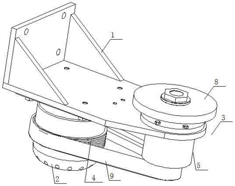
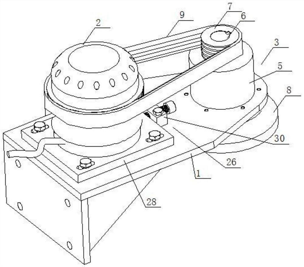
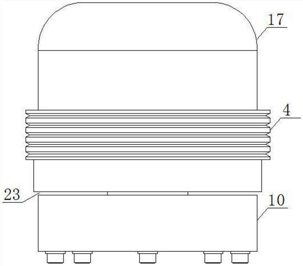
[0023] refer to Figure 1-Figure 8 , a motor transmission processing assembly, comprising a support 1, an outer rotor motor 2 correspondingly installed at both ends of the support 1, a driven grinding device 3, a driving pulley 4 is installed on the outer wall of the outer rotor motor 2, and the driven grinding The cutting device 3 includes a bearing seat 5 fixed on the support 1, a driven shaft 6 connected to the first bearing installed in the bearing seat 5, a driven pulley 7 installed at both ends of the driven shaft 6, and a grinding wheel. Part 8, a drive belt 9 is installed between the driving pulley 4 and the driven pulley 7, the outer rotor 17 drives the driving pulley 4 to rotate, the driving pulley 4 drives the driven pulley 7 and the driven shaft 6 to rotate through the drive belt 9, and is installed on the driven The grinding part 8 at the other end of the shaft 6, such as a grinding wheel, a cutter, etc., rotates, and the grinding part 8 performs grinding, cutting...


PUM


Abstract

The invention discloses a motor transmission machining assembly which comprises a support, an outer rotor motor correspondingly installed at the two ends of the support and a driven grinding device, and a driving belt wheel is installed on the outer wall of an outer rotor of the outer rotor motor. The driven grinding device comprises a bearing seat fixed to the support, a driven shaft connected with a first bearing installed in the bearing seat, driven belt wheels correspondingly installed at the two ends of the driven shaft and a grinding component, and a transmission belt is installed between the driving belt wheel and the driven belt wheels. The length of the whole machine can be reduced, use is convenient, the service life is long, the distance between the motor and the driven grinding device can be conveniently adjusted, and therefore the transmission belt is in the best working state.

Description

technical field [0001] The invention relates to a motor, in particular to a motor transmission processing assembly. Background technique [0002] Electric motor, referred to as motor, is a device that converts electrical energy into mechanical energy. It uses energized coils, that is, stator windings to generate a rotating magnetic field and act on the rotor to form a magnetoelectric force rotating torque. The principle is that the magnetic field acts on the force of the current to make the rotor rotate. In the existing inner rotor motor, the rotor of the motor is arranged in the middle of the stator, and the pulley is installed on the output shaft of the rotor, which results in a longer length of the motor and takes up more space for use; the existing similar motor still has unreasonable structural design, Poor rigidity, inconvenient use and other problems. At present, there is a grinding mechanism driven by a motor, which cannot adjust the distance between the motor and ...

Claims


Application Information

Patent Timeline
Patent Type & Authority Applications(China)
IPC IPC(8): H02K1/12H02K7/00H02K5/173H02K7/10H02K7/14B24B47/12
CPCB24B47/12H02K1/12H02K5/173H02K7/003H02K7/1004H02K7/14
Inventor 马祖添
Owner FOSHAN HUASHUN MOTOR INDUSTRIAL CO LTD
Why Eureka
Try Eureka