
Energy-saving sweeping brush convenient to replace and connecting assembly thereof

A technology for connecting components and sweeping brushes, which is applied in the direction of cleaning carpets, floors, and manual sweeping machines. It can solve problems such as low efficiency and labor-intensive, and achieve the effects of reducing costs, improving efficiency, and stabilizing connections.

Pending Publication Date: 2021-07-23
安徽长中刷业有限公司
View PDF0 Cites 2 Cited by
  • Summary
  • Abstract
  • Description
  • Claims
  • Application Information

AI Technical Summary

Problems solved by technology

[0004] The purpose of the present invention is to solve the problem of labor-intensive and low efficiency in the prior art, and propose an energy-saving sweeping brush and its connection assembly that are easy to replace

Method used


Image

  • Energy-saving sweeping brush convenient to replace and connecting assembly thereof
  • Energy-saving sweeping brush convenient to replace and connecting assembly thereof
  • Energy-saving sweeping brush convenient to replace and connecting assembly thereof

Examples


Embodiment 1

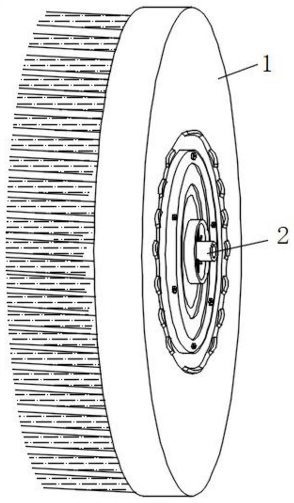
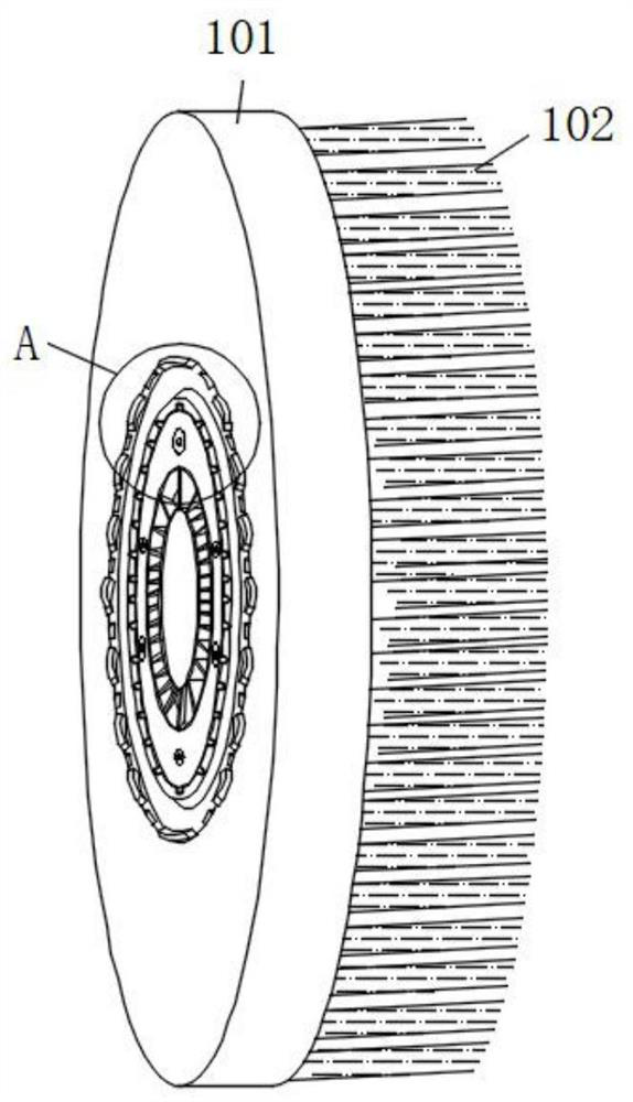
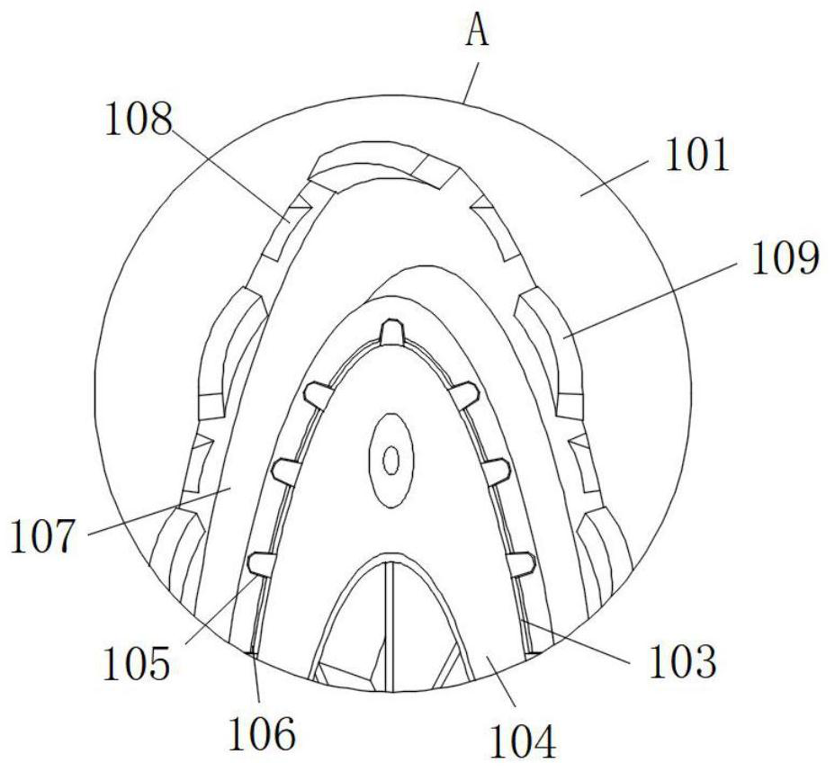
[0034] refer to Figure 1-7 , an energy-saving sweeping brush and its connection assembly that are easy to replace, including a sweeping brush body 1 and a connection assembly 1, the sweeping brush body 1 includes a flocking plate 101, bristles 102 are fixed on one side of the flocking plate 101, and both sides of the center of the flocking plate 101 A mounting hole 103 is opened through the mounting hole 103, and a connecting component 2 104 is clamped in the mounting hole 103. The connecting component 2 104 includes a mounting plate 1041, and the end of the mounting plate 1041 facing away from the bristles 102 is also provided with an annular groove 1044. The inner wall of the annular groove 1044 is fixed. Connected with a spacer 1045, the spacer 1045 divides the annular groove 1044 into a plurality of clamping grooves 1046, and a tapered hole 1047 is opened on both sides of the center of the mounting plate 1041, and a cylindrical groove is formed on the extension of the end ...

Embodiment 2

[0037] Such as image 3 and 4 As shown, this embodiment is basically the same as Embodiment 1. Preferably, the mounting plate 1041 is connected in sliding contact with the inner wall of the mounting hole 103, the outer wall of the mounting plate 1041 is fixed with locking teeth 1042, and the inner wall of the mounting hole 103 is also provided with tooth grooves 105. And latching tooth 1042 is all placed in the draw-in groove, and mounting disc 1041 outer wall also offers cylindrical groove 1, and cylinder 1 inwall is all fixedly installed with electromagnet 1043, and the mounting hole 103 inwall is also fixed with adsorption iron ring 106.

[0038] A plurality of locking teeth 1042 are provided and evenly distributed on the outer wall of the mounting plate 1041 , and the locking teeth 1042 are all slidingly connected in the slots 105 .

[0039] The number of cylindrical slots is one less than that of the locking teeth 1042 and are evenly arranged on the outer wall of the mou...

Embodiment 3

[0042] Such as figure 1 and 2 As shown, this embodiment is basically the same as Embodiment 1. Preferably, there are a plurality of bristles 102 that are evenly distributed in bundles at the middle of one end of the hair-planting plate 101 and at the extension position.

[0043] In this embodiment, a plurality of bristles 102 are arranged and evenly distributed in bundles in the middle and extension of one end of the hair-planting plate 101, thereby increasing the cleaning range of the sweeping brush body 1 and providing a certain guarantee for rapid cleaning of the ground.


PUM


Abstract

The invention discloses an energy-saving sweeping brush convenient to replace and a connecting assembly thereof. The energy-saving sweeping brush convenient to replace comprises a sweeping brush body and a first connecting assembly, the sweeping brush body comprises a bristle planting plate, bristles are fixed to one side of the bristle planting plate, mounting holes are formed in the two sides of the center of the bristle planting plate in a penetrating mode, and a second connecting assembly is clamped in the mounting holes; the second connecting assembly comprises a mounting disc, an annular groove is further formed in the end, away from the bristles, of the middle of the mounting disc, partition blocks are fixedly connected to the inner wall of the annular groove, the annular groove is divided into a plurality of clamping grooves through the partition blocks, conical holes are further formed in the two sides of the center of the mounting disc in a penetrating mode, and a second cylindrical groove is further formed in the outer edge of the end, away from the bristles, of the mounting disc. Second electromagnets are fixedly connected to the inner bottom surface of the second cylindrical groove; and a drainage groove is further formed in the middle of one end, deviating from the bristles, of the bristle planting plate. The sweeping brush is reasonable in design and stable in connection, the floor sweeping brush is convenient to disassemble and assemble, the floor sweeping efficiency is greatly improved, the connecting piece in the middle of the floor sweeping brush can be reused, and the manufacturing cost of the floor sweeping brush is greatly saved.

Description

technical field [0001] The invention relates to the technical field of brush body connection, in particular to an energy-saving floor sweeping brush and a connection assembly thereof which are easy to replace. Background technique [0002] There are three types of sweeping brushes: cylindrical, conical and belt. The cylindrical brush is composed of a brush core, bristles and parts that fix the bristles to the brush core. The bristles are generally densely arranged in bundles along the cylindrical surface of the brush core. The outer diameter of the cylindrical brush is reduced due to the wear of the bristles, and sometimes a diameter adjustment mechanism is set. The bristles are usually made of steel wire, broken flat bamboo strips, artificial fibers and other materials. The steel wire has high wear resistance. The belt brush is composed of two roller chains. , two driving sprockets and guide wheels, and a toothed belt form a flat brush, with large contact area between the b...

Claims


Application Information

Patent Timeline
Patent Type & Authority Applications(China)
IPC IPC(8): A47L11/24A47L11/40A46B7/08A46B9/12
CPCA47L11/24A47L11/4038A46B7/08A46B9/12A47L2201/00A46B2200/3033
Inventor 王小剑
Owner 安徽长中刷业有限公司
Learn More