Portable microwave imaging system

A microwave imaging, portable technology, applied in radio wave measurement system, radio wave reflection/re-radiation, utilization of re-radiation, etc., can solve the problems of fixed scanning trajectory, low flexibility of equipment, and incapability of real-time imaging, etc., to increase flexibility Accuracy, cost reduction, ease of production and commercial promotion

Active Publication Date: 2021-07-23
NANJING UNIV OF POSTS & TELECOMM
View PDF12 Cites 2 Cited by
  • Summary
  • Abstract
  • Description
  • Claims
  • Application Information

AI Technical Summary

Problems solved by technology

[0004] The purpose of the present invention is to provide a portable microwave imaging system with simple structure and real-time imaging for the problems of low equipment flexibility, incapable of real-time imaging, fixed scanning angle and fixed scanning track in the existing security inspection technology.

Method used


Image

  • Portable microwave imaging system
  • Portable microwave imaging system
  • Portable microwave imaging system

Examples


Embodiment 1

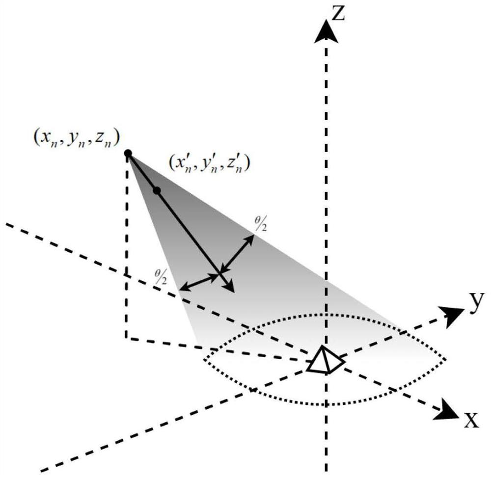
[0062] Embodiment 1 illustrates the specific working principle of the system. In this embodiment, the test signal is set as a broadband signal with a center frequency of 30 GHz, a bandwidth of 5 GHz, and a sampling rate of 5 MHz. Spatial layout such as figure 2 As shown in , it is assumed that the corner reflector to be measured (the object to be detected) is located at the origin of the Cartesian coordinate system, and the directions of the three axes are determined. The handheld scanner is located at any position in space, and the object to be detected must be within the effective scanning angle of the scanner, otherwise the on-off judge control system is in a standby state and stops working, so the embodiment defaults that the object to be detected is within the effective angle.

[0063] Suppose the scanner is at (x n ,y n ,z n ), the center point of the scanning angle is (x′ n ,y′ n ,z' n ), so the scan direction vector is in The effective scan angle is fixed a...

Embodiment 2

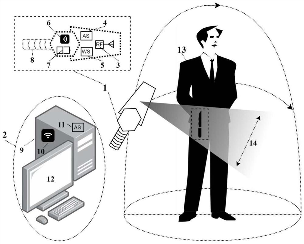
[0066] This implementation provides the specific operation mode of the portable microwave imaging system, such as image 3 shown. The test signal is set as a broadband signal with a center frequency of 62GHz, a bandwidth of 5GHz, a linear change in frequency, and a sampling rate of 5MHz. The object to be measured is a human body. The operator needs to hold the scanner and make the scanning direction face the human body. Within a scanning interval, the instantaneous position and echo signal of the scanner are obtained and transmitted to the signal processor. Wave signal coherent Fourier transformation, conical area back projection calculation operation, for the first time real-time three-dimensional image can be obtained and displayed on the monitor around the operator.

[0067] If the operator continues to scan sensitive parts such as clothes pockets or trousers pockets for a long time, the details of this part will be clearer in the 3D image of the monitor, and the contrast...


PUM


Abstract

The invention discloses a portable microwave imaging system which comprises a handheld active scanner and an information processing terminal. The handheld active scanner comprises a radio frequency transceiver, a first attitude sensor, an on-off judgment device and a first wireless transceiving module; and the information processing terminal comprises an information processor and a second wireless transceiver module and is used for receiving return data of the scanner. In one instantaneous sampling process, the spatial attitude and echo signals of the scanner are received by the information processing terminal, real-time back projection image reconstruction is carried out, and the reconstructed image is accumulated on the previous image. According to the invention, the image is reconstructed through real-time back projection of the space coordinate and angle determined by the attitude sensor, the handheld scanner can be located at any position, the equipment limitation of traditional array imaging is broken, the use flexibility and coverage angle of the equipment are greatly improved, the hardware cost is reduced, real-time imaging can be satisfied, and the detection efficiency is improved.

Description

technical field [0001] The invention relates to the technical field of security inspection imaging, in particular to a portable microwave imaging system. Background technique [0002] The existing main security inspection methods are manual inspection, metal detection equipment and X-ray security inspection machine. The manual inspection method using metal detectors has the problem of low efficiency and there is a certain possibility of infringing on personal privacy due to physical contact, while X-rays cannot directly act on the human body due to ionization characteristics. The millimeter-wave security imaging can not only detect hidden metal objects under the fabric, but also detect dangerous goods such as plastic guns, ceramic knives, explosives, etc., without electromagnetic radiation hazards to the human body. Millimeter wave security inspection can obtain clear image information, which can greatly reduce the false alarm rate, so it has attracted much attention in rec...

Claims


Application Information

Patent Timeline
Patent Type & Authority Applications(China)
IPC IPC(8): G01S13/89
CPCG01S13/89
Inventor 邵文渊郭稼逸金秀华黄晓东
Owner NANJING UNIV OF POSTS & TELECOMM
Why Eureka
Try Eureka