Mini LED dodging sheet, preparation process thereof, and backlight module

A preparation process and backlight module technology, which is applied in optics, optical components, nonlinear optics, etc., can solve problems such as poor visual effect, limited light divergence angle, and inability to guarantee, so as to reduce the demand of Mini LED power and improve assembly efficiency and the difficulty of assembly, the effect of reducing power consumption and heat dissipation

Pending Publication Date: 2021-07-23
NICROTEK +2
View PDF0 Cites 0 Cited by
  • Summary
  • Abstract
  • Description
  • Claims
  • Application Information

AI Technical Summary

Problems solved by technology

[0003] The divergence angle of the light emitted by a single Mini-LED point light source is limited, so that the energy in the central area of ​​the light emitting surface is greater than the energy in the surrounding area, and the distance between the chips is about 1mm-4mm, so the array light composed of multiple LED chips will make the screen There are periodic light and dark areas on the screen, the visual effect is poor, and the user experience is affected
Traditional technology usually covers the diffusion film based on diffusion particles on the exit surface of the Mini-LED to achieve light diffusion and light mixing, so as to achieve uniform light output on the exit surface. However, the light mixing distance corresponding to this method is several millimeters to several The range of 1 cm does not meet the requirements of thinner and lighter display industry in the future.
[0004] Although there are many types of dodging sheets on the market, the balance between the haze and light transmittance of the dodging sheet is not good enough, and there is no guarantee that a good light transmittance can be guaranteed when the haze reaches a certain level.
Especially in the preparation of some thick dodging sheets, in order to achieve a certain haze in the manufacturing process, a large number of diffusing particles are often added to the preparation material, and the diffusing particles absorb light, which will affect the light transmittance of the dodging sheet
However, if the light transmittance is not high, a large backlight power will be required, which will consume a lot of energy and affect the service life of the lamp beads.
In some existing technologies, the structures on both sides of the dodging film are pyramids, prisms or orthogonal cylinders, which are processed by diamond lathes. At least two layers of film are needed to achieve the dodging effect, and alignment is required. Orthogonal stacking, very inconvenient when assembling the backlight module
There are also some existing technologies that form convex and concave points by coating glass beads on the dodging plate substrate. During the formation process, there will be optical glue, which will affect the light transmittance of the dodging plate.
There is also a composite film used in the prior art, which is obtained by bonding two uniform films with a prism or glass bead structure on one side. The thickness is relatively large, and it is not suitable for ultra-thin devices.

Method used


Image

  • Mini LED dodging sheet, preparation process thereof, and backlight module
  • Mini LED dodging sheet, preparation process thereof, and backlight module
  • Mini LED dodging sheet, preparation process thereof, and backlight module

Examples


Embodiment 1

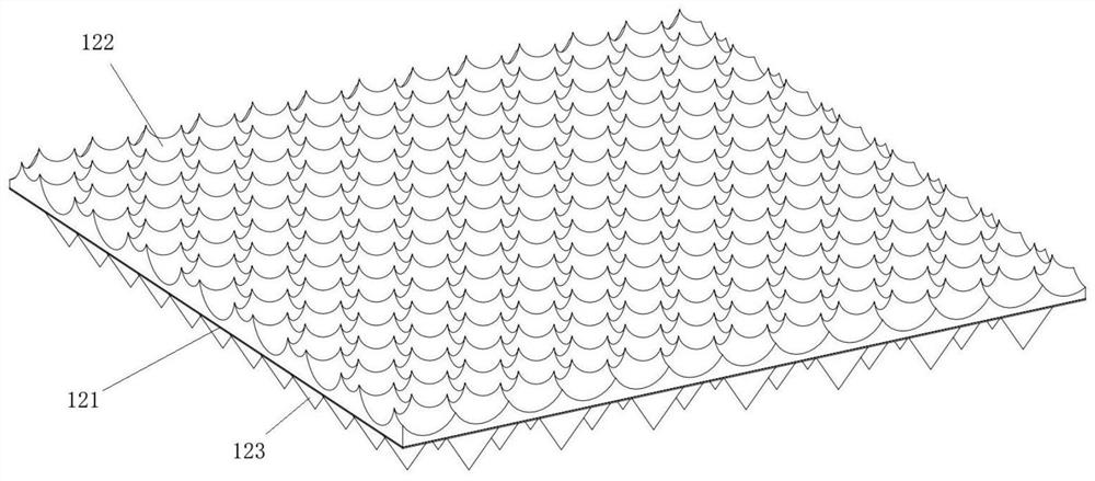
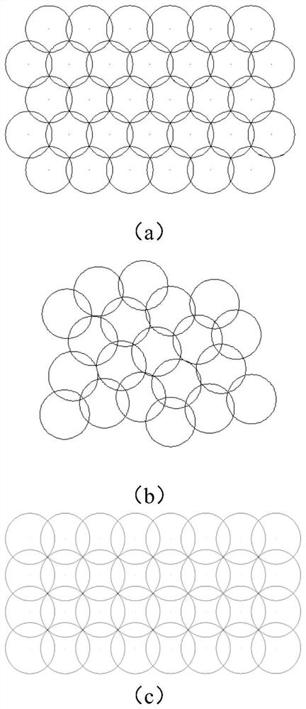
[0049] This embodiment provides a Mini LED dodging sheet, which includes a base 121 , several microlens structures 122 on one side of the base 121 , and a convex mirror structure on the other side of the base 121 . Such as figure 1 As shown, the microlens structure 122 shown in the figure is a circular concave structure 1221 . The concave surface of the microlens structure 122 is preferably a curved surface. Several microlens structures 122 are arranged in multiple rows, and several microlens structures 122 in two adjacent rows are arranged in a staggered manner, such as figure 2 as shown in a, or arranged randomly, such as figure 2 As shown in b, or orthogonal arrangement, such as figure 2 as shown in c. Partial overlap between two adjacent microlens structures 122, such as figure 2 a-2c and image 3 shown. The overlapping range between adjacent microlens structures 122 is 5%-25%, preferably 10%. Adjacent microlens structures 122 are partially overlapped, on the o...

Embodiment 2

[0072] The difference between this embodiment and the first embodiment is that the microlens structure 122 on one side of the dodging sheet in this embodiment is a circular convex structure 1222 . The protruding surface of the microlens structure 122 is preferably a curved surface. Such as Figure 21 to Figure 24 The dodging sheet schematically shown has a raised microlens structure 122 on one side and a conical convex mirror body 123 on the other side. or as Figure 25 and Figure 26 The dodging sheet schematically shown has a raised microlens structure 122 on one side and a quadrangular pyramid-shaped convex lens body 123 on the other side. The preparation method of the dodging sheet and the structure of the backlight module in this embodiment are the same as in Embodiment 1, and will not be repeated here.


PUM

PropertyMeasurementUnit
Heightaaaaaaaaaa
Thicknessaaaaaaaaaa
Heightaaaaaaaaaa

Abstract

The invention discloses a Mini LED dodging sheet, a preparation process thereof and a backlight module, the dodging sheet comprises a substrate, a plurality of micro lens structures arranged at one side of the substrate and a convex lens structure arranged at the other side of the substrate, the plurality of micro lens structures are arranged in a plurality of rows, and the convex lens structure is arranged on the other side of the substrate. The multiple micro-lens structures in two adjacent rows are arranged in a staggered mode or a random mode or an orthogonal mode, the two adjacent micro-lens structures are partially overlapped, each micro-lens structure comprises a concave structure and / or a convex structure, and the convex lens structure comprises multiple convex lens bodies with set shapes. According to the Mini LED dodging sheet, the micro lens structure is arranged at one side of the Mini LED dodging sheet, the convex lens structure is arranged at the other side of the Mini LED dodging sheet, so that a lamp bead panel emits light uniformly, the utilization efficiency of the light is improved, the light transmittance is enhanced while the haze is guaranteed, the superposition photoetching technology is adopted, and the duty ratio of the micro lens structure on the Mini LED dodging sheet can reach 100%.

Description

technical field [0001] The present invention relates to the technical field of backlight display, in particular to a Mini LED uniform light sheet, a preparation process thereof, and a backlight module. Background technique [0002] Most of the liquid crystal display devices currently on the market are backlight displays, which include a housing, a liquid crystal panel disposed in the housing, and a backlight module disposed in the housing. Since the liquid crystal panel itself does not emit light, it needs to use the light source provided by the backlight module to display images normally. Therefore, the backlight module is one of the key components of the liquid crystal display. The backlight module is mainly composed of lamp beads and dodging film. Compared with traditional LED backlights, Mini LEDs are more suitable as backlights for high-end LCD displays, with the advantages of smaller size, higher brightness, faster response, and local dimming. [0003] The divergenc...

Claims


Application Information

Patent Timeline
IPC IPC(8): G02B3/00G02B5/02G02F1/13357
CPCG02B3/0006G02B3/0012G02B5/0226G02B5/0242G02B5/0268G02F1/133606
Inventor 方宗豹张恒陈林森周欣管昊远司群英
Owner NICROTEK
Why Eureka
Try Eureka