Coding Planar Target for Camera Calibration and Its Decoding Method

A technology of planar target and decoding method, which is applied in the field of coding planar target for camera calibration and its decoding, which can solve the problems of camera calibration, lack of flexibility, and difficulty in moving, etc., to remove noise interference, improve flexibility, and fast decoding speed Effect

Active Publication Date: 2022-08-09
HEFEI UNIV OF TECH
View PDF6 Cites 0 Cited by
  • Summary
  • Abstract
  • Description
  • Claims
  • Application Information

AI Technical Summary

Problems solved by technology

[0003] In order to complete the camera calibration, it is necessary to calibrate the target. For example, Roger Tsai proposed a camera calibration algorithm based on radial constraints in 1896. This algorithm uses a three-dimensional target. Although the 3D three-dimensional target can achieve camera calibration and solve the camera inside and outside parameters, but it is large in size, lacks certain flexibility, and is not easy to move; Zhang Zhengyou (Z.Y Zhang) gave a camera calibration algorithm based on a planar target in 1999, using a relatively simple planar target to make the calibration process easier. Flexible, but the planar target does not contain any coding and directional information, and in the actual calibration process, the camera often fails to capture a complete target image. At this time, the traditional planar checkerboard target that does not contain coding information cannot Carry out camera calibration

Method used


Image

  • Coding Planar Target for Camera Calibration and Its Decoding Method
  • Coding Planar Target for Camera Calibration and Its Decoding Method
  • Coding Planar Target for Camera Calibration and Its Decoding Method

Examples


Embodiment Construction

[0214] The preferred embodiments of the present invention will be described in detail below with reference to the accompanying drawings, so that the advantages and features of the present invention can be more easily understood by those skilled in the art, and the protection scope of the present invention can be more clearly defined.

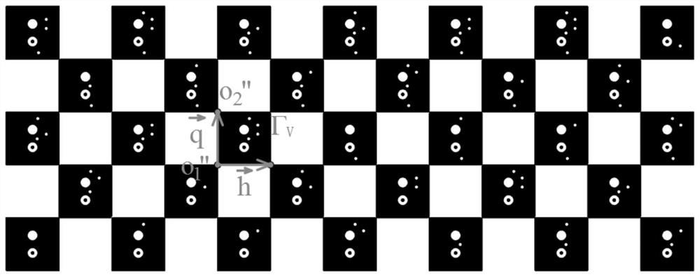
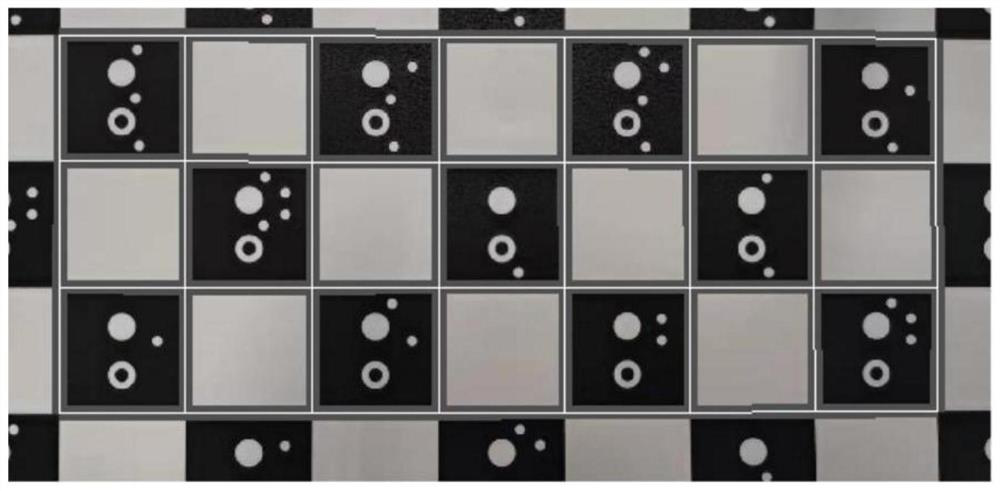
[0215] see figure 1 , a coding plane target for camera calibration, the coding plane target is composed of a coding checkerboard composed of parallelogram coding units and parallelogram non-coding units alternately, and the coding plane target takes the intersection of parallelogram coding units connected at any diagonal angle as to encode the calibration corners of the planar target, figure 1 The coding plane target shown contains a total of 4 rows × 12 columns of calibration corner points; a coding pattern is provided inside each parallelogram coding unit in the coding plane target, and the coding pattern includes a positioning pattern, an ori...


PUM


Abstract

The invention discloses a coding plane target for camera calibration and a decoding method thereof. The coding plane target comprises a coding checkerboard composed of parallelogram coding units and parallelogram non-coding units alternately. The intersection of the parallelogram coding units connected by the corners is used as the calibration corner point of the coding plane target; each parallelogram coding unit in the coding plane target is provided with a coding pattern, and the coding pattern includes a positioning pattern, an orientation pattern and a coding mark pattern; The decoding method can quickly and accurately obtain the matching relationship between the sub-pixel coordinates of the demarcated corner points on the coding plane target in the image, the corresponding coding sequence number of the demarcated corner points, and the target coordinates of the corresponding demarcated corner points by means of digital image processing; the present invention proposes The encoding plane target and its decoding method can be used in the field of camera internal and external parameter calibration.

Description

technical field [0001] The invention relates to the field of camera calibration in the field of computer vision, in particular to a coding plane target for camera calibration and a decoding method thereof, which are used for monocular camera calibration, binocular camera calibration and multi-vision system calibration. Background technique [0002] Computer vision is widely used in control engineering, optics, surveying and many other fields. The primary and fundamental problem that computer vision needs to solve is camera calibration. Camera calibration is a major difficulty in computer vision measurement technology research; its ultimate purpose is to Solve the internal and external parameters of the camera and find the corresponding relationship between the pixel coordinates and the world coordinates; therefore, the camera calibration technology has received more extensive attention and has also been developed rapidly. [0003] In order to complete the camera calibration,...

Claims


Application Information

Patent Timeline
Patent Type & Authority Patents(China)
IPC IPC(8): G06T7/80G06T5/30G06T7/187G06T7/70
CPCG06T7/80G06T7/187G06T7/70G06T5/30G06T2207/30244
Inventor 殷玉龙朱华炳杨昭辉杨霈
Owner HEFEI UNIV OF TECH
Why Eureka
Try Eureka