Driving method and driving circuit for piezoelectric ceramic actuator

A technology of piezoelectric ceramics and driving circuits, which is applied in the direction of piezoelectric effect/electrostriction or magnetostriction motors, generators/motors, instruments, etc., and can solve the problems that high precision and low ripple voltage output cannot be taken into account at the same time

Active Publication Date: 2021-07-23
HUAZHONG UNIV OF SCI & TECH
View PDF6 Cites 2 Cited by
  • Summary
  • Abstract
  • Description
  • Claims
  • Application Information

AI Technical Summary

Problems solved by technology

[0005] The present invention provides a piezoelectric ceramic actuator driving method and a driving circuit to solve the problem that the existing piez

Method used


Image

  • Driving method and driving circuit for piezoelectric ceramic actuator
  • Driving method and driving circuit for piezoelectric ceramic actuator
  • Driving method and driving circuit for piezoelectric ceramic actuator

Examples


Embodiment 1

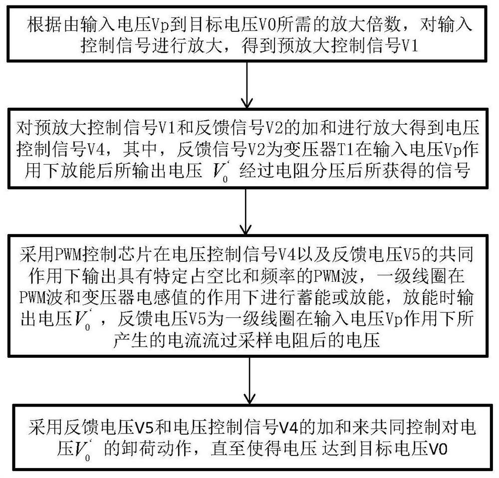
[0038] A piezoelectric ceramic actuator driving method 100, such as figure 1 shown, including:

[0039] Step 110, amplifying the input control signal according to the required amplification factor from the input voltage Vp to the target voltage V0 to obtain the pre-amplification control signal V1;

[0040] Step 120, amplify the sum of the pre-amplification control signal V1 and the feedback signal V2 to obtain the voltage control signal V4, wherein the feedback signal V2 is the output voltage V of the transformer T1 after it is discharged under the action of the input voltage Vp 0 'The signal obtained after resistive voltage division;

[0041] Step 130: Using the PWM control chip to output a PWM wave with a specific duty cycle and frequency under the combined action of the voltage control signal V4 and the feedback voltage V5, the primary coil stores or discharges energy under the action of the PWM wave and the inductance value of the transformer can, output voltage V when d...

Embodiment 2

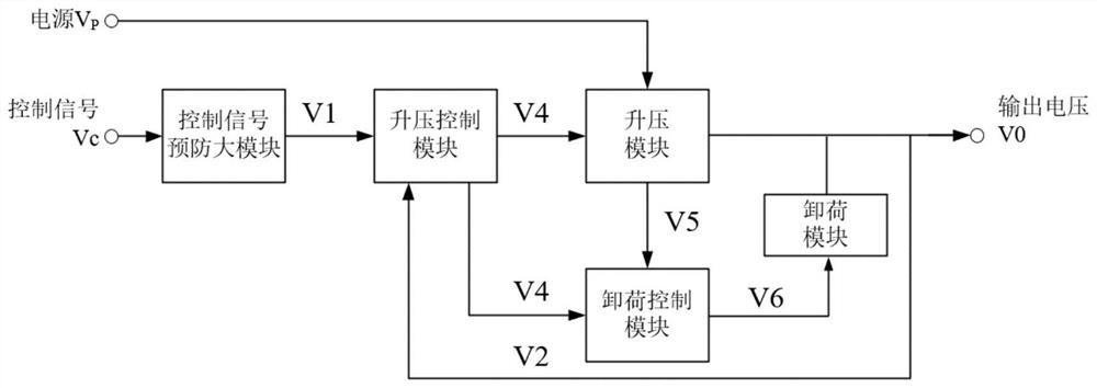
[0047] A piezoceramic actuator drive circuit such as figure 2 As shown, it includes: a control signal pre-amplification module, a boost control module, a boost module, an unload control module, and an unload module. The control signal pre-amplification module is used to amplify the input control signal according to the amplification factor required from the input voltage Vp to the target voltage V0 to obtain the pre-amplification control signal V1; the boost control module is used for the pre-amplification control signal V1 and feedback The sum of the signal V2 is amplified to obtain the voltage control signal V4, and the feedback signal V2 is the output voltage V of the boost module 0 'The signal obtained after the resistor divides; the boost module includes a PWM control chip and a transformer T1, where the PWM control chip outputs a PWM wave with a specific duty cycle and frequency under the joint action of the voltage control signal V4 and the feedback voltage V5 , the p...


PUM


Abstract

The invention belongs to the technical field of circuit control of piezoelectric ceramic actuators, and particularly relates to a driving method and driving circuit for a piezoelectric ceramic actuator. The method comprises the following steps: amplifying an input control signal to obtain a pre-amplification control signal V1; amplifying the sum of the V1 and a feedback signal V2 to obtain a voltage control signal V4, wherein the V2 is a signal obtained after voltage V0', which is output after a transformer T1 releases energy under the action of input voltage Vp, is divided by a resistor; calculating a PWM wave with a specific duty ratio by using a PWM control chip based on the V4 and feedback voltage V5, and allowing a primary coil to store energy or release energy under the action of the PWM wave and the inductance value of the transformer, wherein the voltage V0' is output during energy release, and the V5 is the voltage generated after current generated by the primary coil under the action of the Vp flows through a sampling resistor; and jointly controlling the unloading action of the voltage V0' by adopting the sum of V5 and V4 until the voltage V0 'reaches a target voltage. According to the method, in continuous adjustment of unloading action and boost control, the control precision of output voltage can be effectively improved, and output ripples can be reduced.

Description

technical field [0001] The invention belongs to the technical field of circuit control of a piezoelectric ceramic actuator, and more particularly relates to a driving method and a driving circuit of a piezoelectric ceramic actuator. Background technique [0002] Piezoelectric ceramic actuator is a new type of micro-displacement device developed in recent years. It has the characteristics of small size, large thrust, high precision and displacement resolution, and fast frequency response. It has no noise and no heat during use. It is an ideal The micro displacement device has been widely used in the fields of aerospace, microelectronics, precision measurement, bioengineering, robotics and precision machining. Its application based on the inverse piezoelectric effect has been relatively extensive, but according to specific application scenarios (such as speed feedback control in vibration reduction systems), its driving voltage usually requires high precision and a wide range ...

Claims


Application Information

Patent Timeline
IPC IPC(8): H02M3/335H02M1/08H02N2/00
CPCH02M3/33576H02M1/08H02N2/0075
Inventor 张争光李小清李嘉辉周游陈学东
Owner HUAZHONG UNIV OF SCI & TECH
Why Eureka
Try Eureka