Single-fiber bidirectional optical module

A single-fiber bidirectional, optical module technology, applied in the field of optical communication, can solve the problems of complex assembly process, large number of parts, and difficult reduction of overall size

Pending Publication Date: 2021-07-23
武汉恩达通科技有限公司
View PDF5 Cites 0 Cited by
  • Summary
  • Abstract
  • Description
  • Claims
  • Application Information

AI Technical Summary

Problems solved by technology

[0002] The existing three-port circulators on the market are generally assembled with magnetic rings. There are assembly gaps between each crystal, the number of parts is large, the assembly process is complicated, and the assembly is difficult. The overall size of this type of design structure is not easy to reduce. The distance between the output end and the input end is difficult to adjust, errors are prone to occur during the assembly process, the optical path is long, and the optical signal is easy to lose
In addition, the conventional technology usually adopts components to be bonded to the third carrier platform for optical coupling. There is a gap in the middle of the light-passing part, which has poor stability and affects performance. The effect of the optical signal is poor and the cost is high.
And, the conventional WDM wavelength division multiplexing technology BIDI optical module needs to use the wavelength division multiplexing filter, the WDM wavelength division multiplexing technology BIDI optical module must be used in pairs when used, the operation of two WDM duplexers The wavelengths must also be complementary and consistent, which limits the use

Method used


Image

  • Single-fiber bidirectional optical module
  • Single-fiber bidirectional optical module
  • Single-fiber bidirectional optical module

Examples


Embodiment Construction

[0042] The following description serves to disclose the present invention to enable those skilled in the art to carry out the present invention. The preferred embodiments described below are only examples, and those skilled in the art can devise other obvious variations. The basic principles of the present invention defined in the following description can be applied to other embodiments, variations, improvements, equivalents and other technical solutions without departing from the spirit and scope of the present invention.

[0043] Those skilled in the art should understand that in the disclosure of the present invention, the terms "vertical", "transverse", "upper", "lower", "front", "rear", "left", "right", " The orientation or positional relationship indicated by "vertical", "horizontal", "top", "bottom", "inner", "outer", etc. is based on the orientation or positional relationship shown in the drawings, which are only for the convenience of describing the present invention...


PUM


Abstract

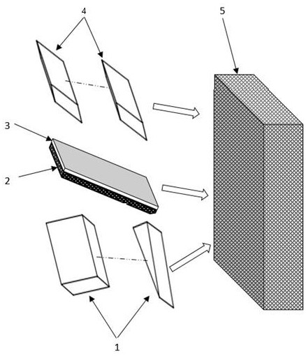
The invention discloses a single-fiber bidirectional optical module which comprises a three-port circulator, an optical fiber interface, a transmitting device and a receiving device, the optical fiber interface is arranged on the three-port circulator, the transmitting device is arranged towards the three-port circulator, and the receiving device is arranged towards the three-port circulator. The transmitting device is arranged towards the three-port circulator so that the three-port circulator can receive the light waves transmitted by the transmitting device, and the receiving device is arranged towards the three-port circulator so that the receiving device can receive the light waves from the three-port circulator.

Description

technical field [0001] The invention relates to the field of optical communication, in particular to a single-fiber bidirectional optical module. Background technique [0002] The existing three-port circulators on the market are generally assembled with magnetic rings. There are assembly gaps between each crystal, the number of parts is large, the assembly process is complicated, and the assembly is difficult. The overall size of this type of design structure is not easy to reduce. It is difficult to adjust the distance between the output end and the input end, errors are prone to occur during the assembly process, the optical path is long, and the optical signal is easy to be lost. In addition, the conventional technology usually adopts components to be bonded to the third carrier platform for optical coupling. There is a gap in the middle of the light-passing component, which has poor stability, affects performance, poor optical signal effect, and high cost. And, the con...

Claims


Application Information

Patent Timeline
IPC IPC(8): H04B10/25
Inventor 顾共恩张美容樊恒志
Owner 武汉恩达通科技有限公司
Why Eureka
Try Eureka